

Introduction of CNC wire saw machine Installation
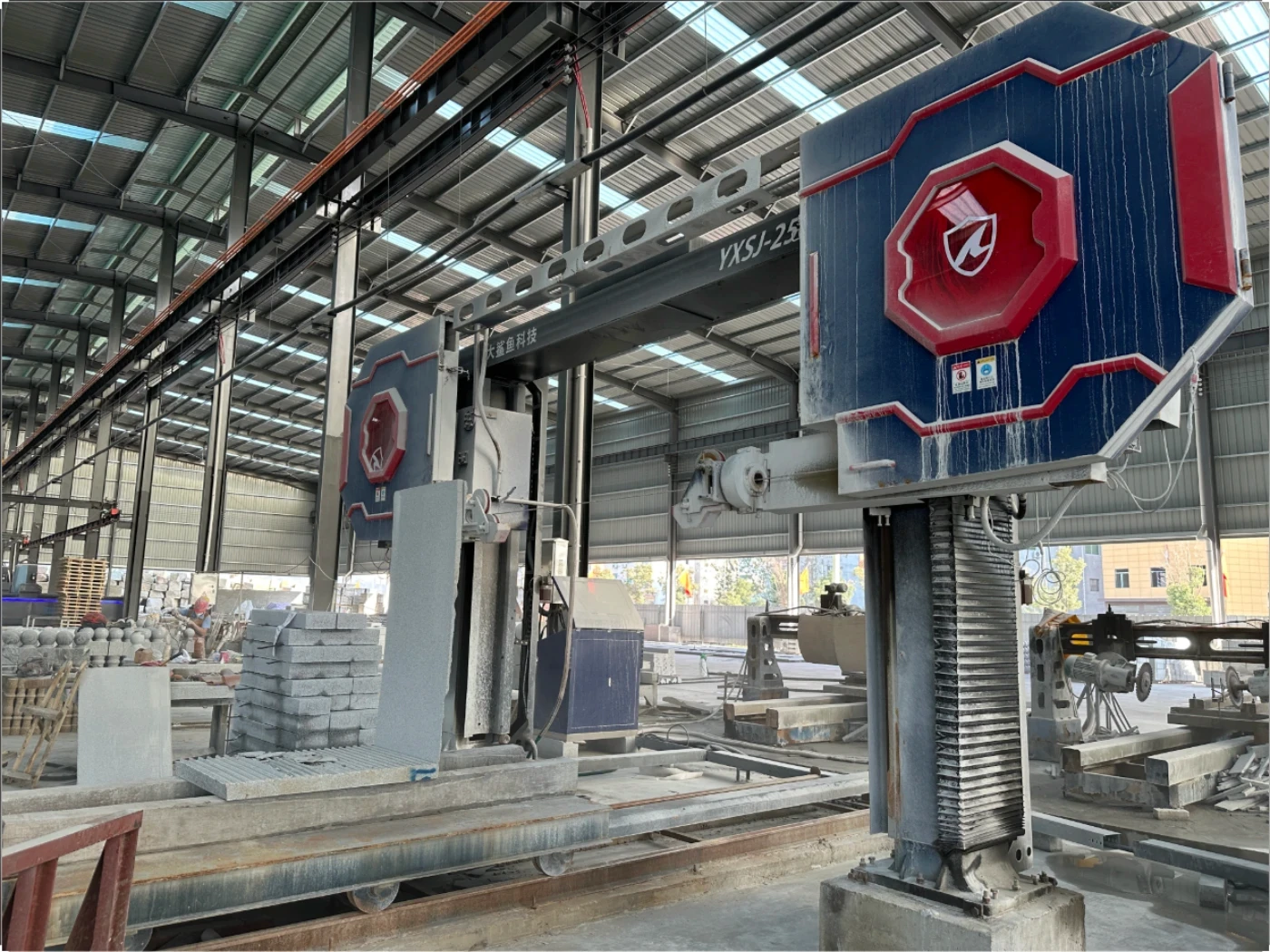
Hello, this article is designed to guide you through the process of installing a CNC wire saw machine, using the YXSJ-4000 model as an example. Although there may be some differences in details among different models of CNC wire saw machines, the basic installation steps are generally similar, including securing the base, installing the uprights, crossbeams, guide wheels, and flywheels, which are key stages. We hope this information will be helpful to you.
Fix the column base of CNC wire saw machine
This step does not require a video.
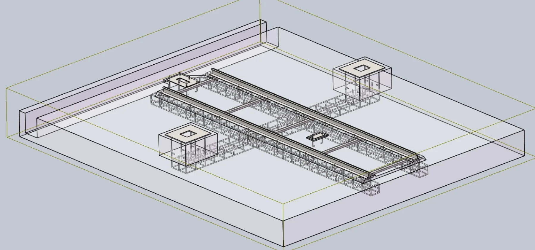
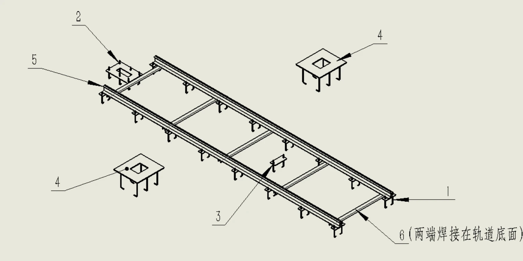
Install the provided embedded parts in the foundation according to the foundation drawing and fix them with concrete.
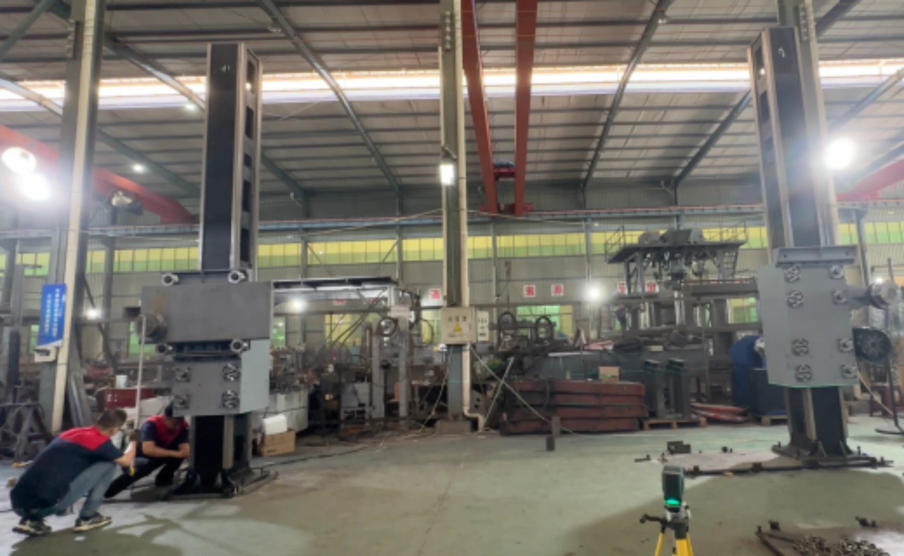
Install and fix the columns of CNC wire saw machine
Same on both sides.
Lift the columns to the embedded parts position
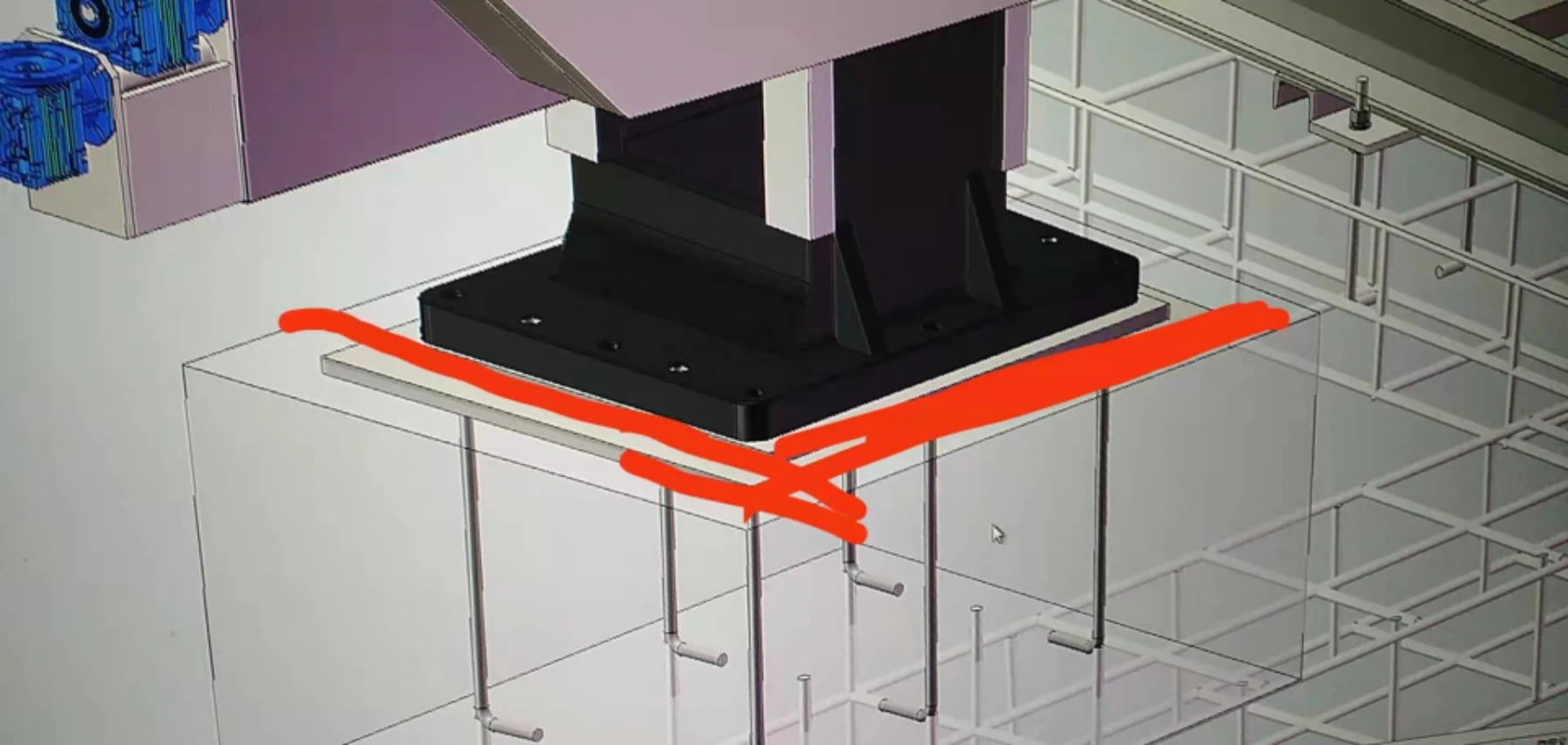
The one with the motor is the right column. The one with the hydraulic station is the left column. Fix the column position according to the hole position. First insert the screw to test whether it is aligned with the hole position.
Fix the position
Install the column to the predetermined base position and tighten the screw bolt. Do not tighten too much. Fine-tuning will be required later.
Calibrate the verticality of the column
The calibration steps for the left and right columns are the same.
Put the gradienter device on the vertical plane of the column track, and then check whether the bubble is centered. If not, adjust the tightness of the base horizontal screw to achieve the verticality of the column; the front and side need to be calibrated (as shown below) to ensure that both directions are vertical as follow picture:
Verticality calibration on the outer side of the column
Verticality calibration on the front side of the column
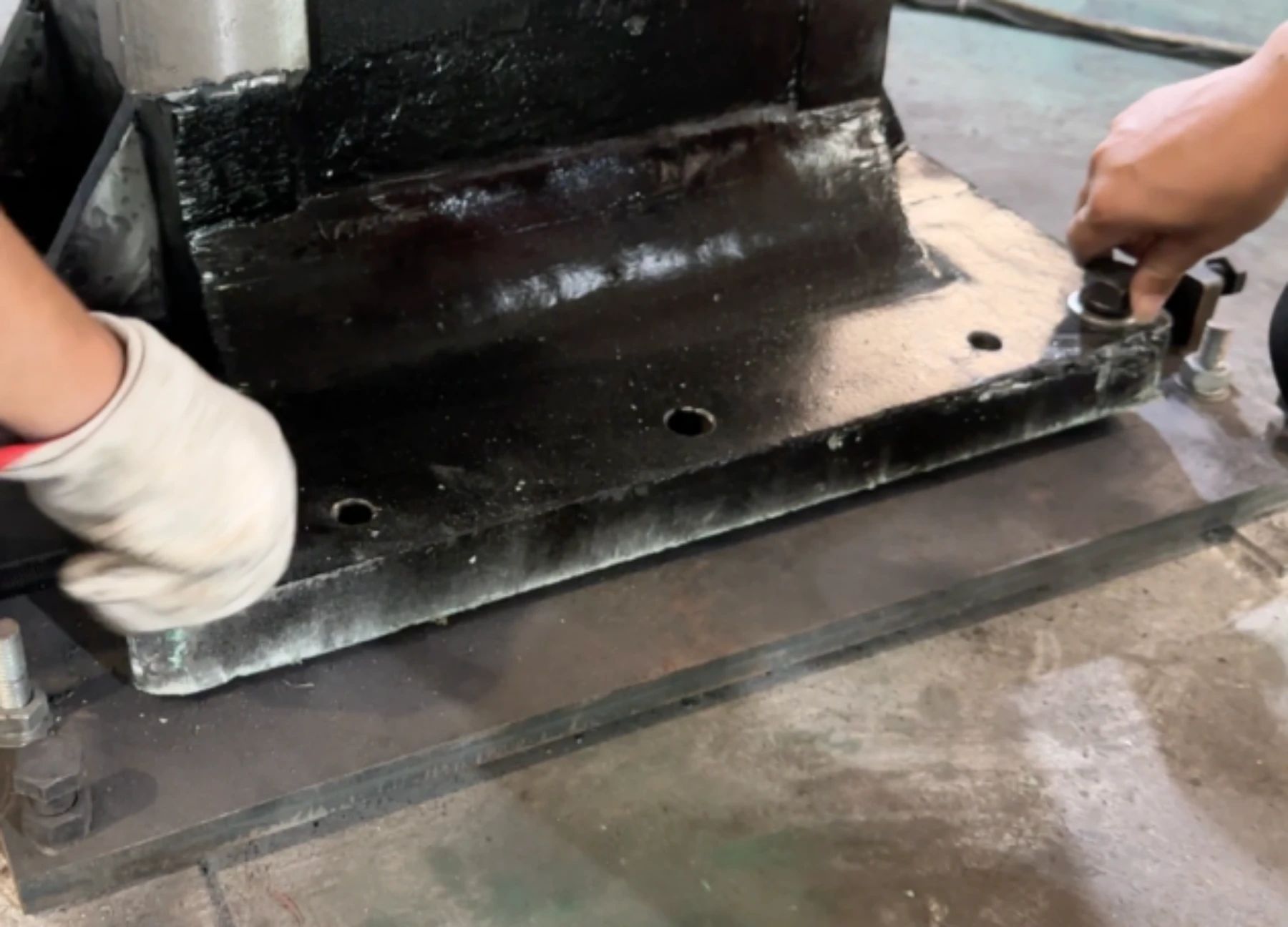
Install the accessory iron plate
The small iron sheets on the four sides of the iron plate are welded to the four corners of the column according to the size of the column, which can be used to fine-tune the position of the column and fix the column later. As follow pictures:
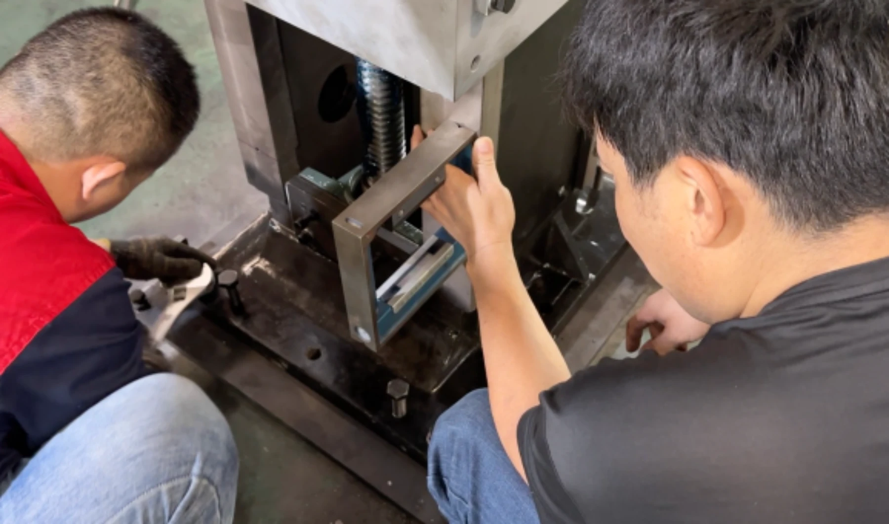
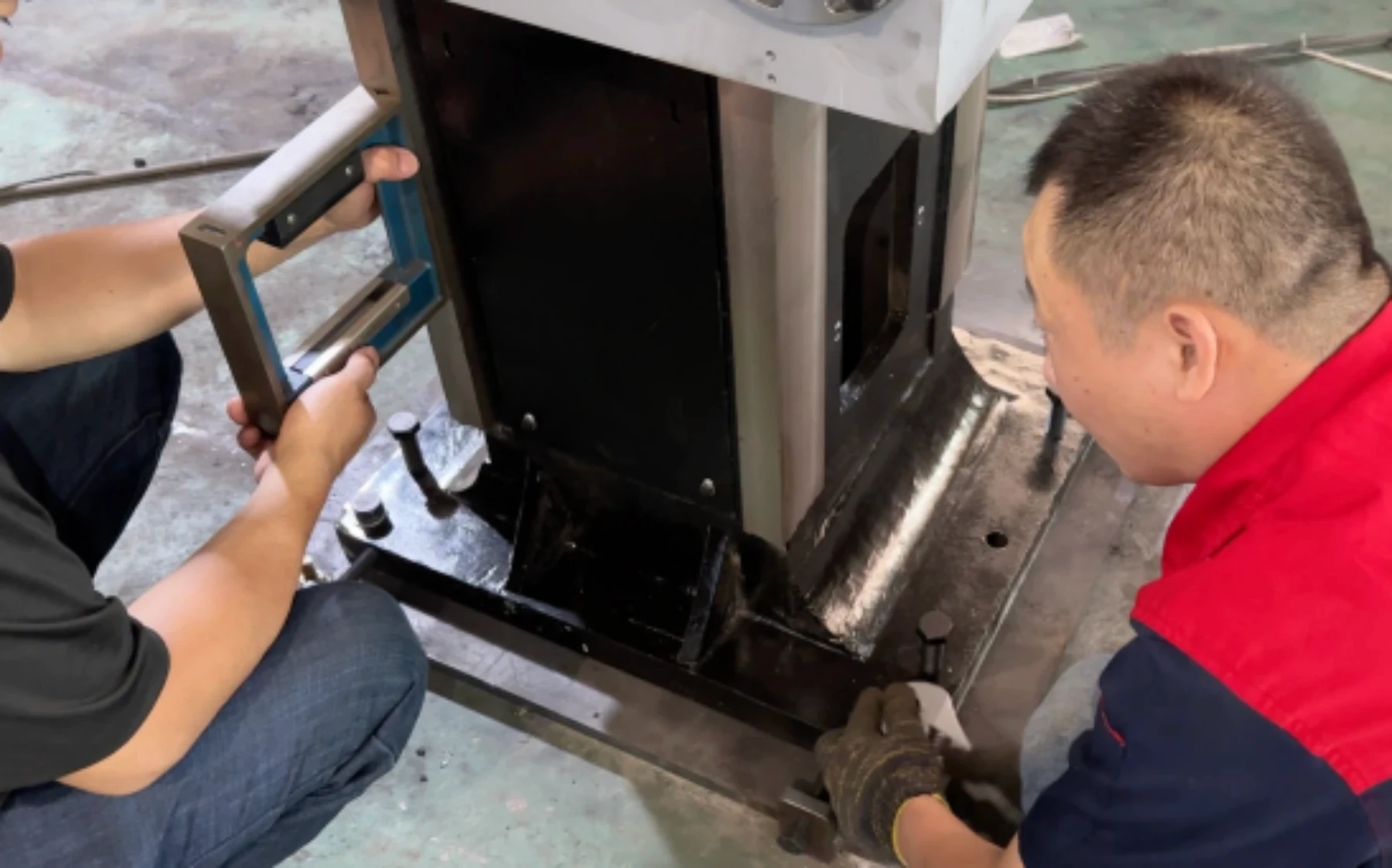
Calibrate the parallelism of the column body
Prepare tools: wire, 3 gaskets of same size
Take the front of the square box as the reference and draw a straight line horizontally from one side to the other side, and put gasket between the square box and the straight line to fix the thickness (both the outer sides of the columns are required) as shown below:
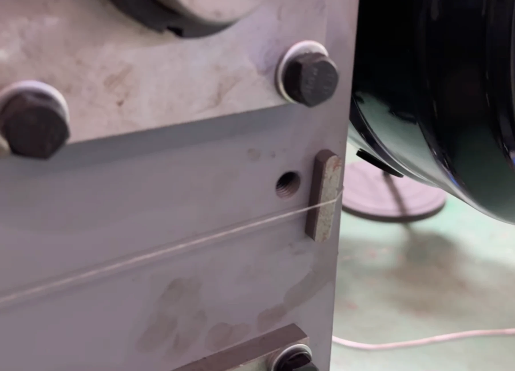
put gasket between the line and the square box to check if it fits. The inside of both columns need to be measured.As shown in the figure below:
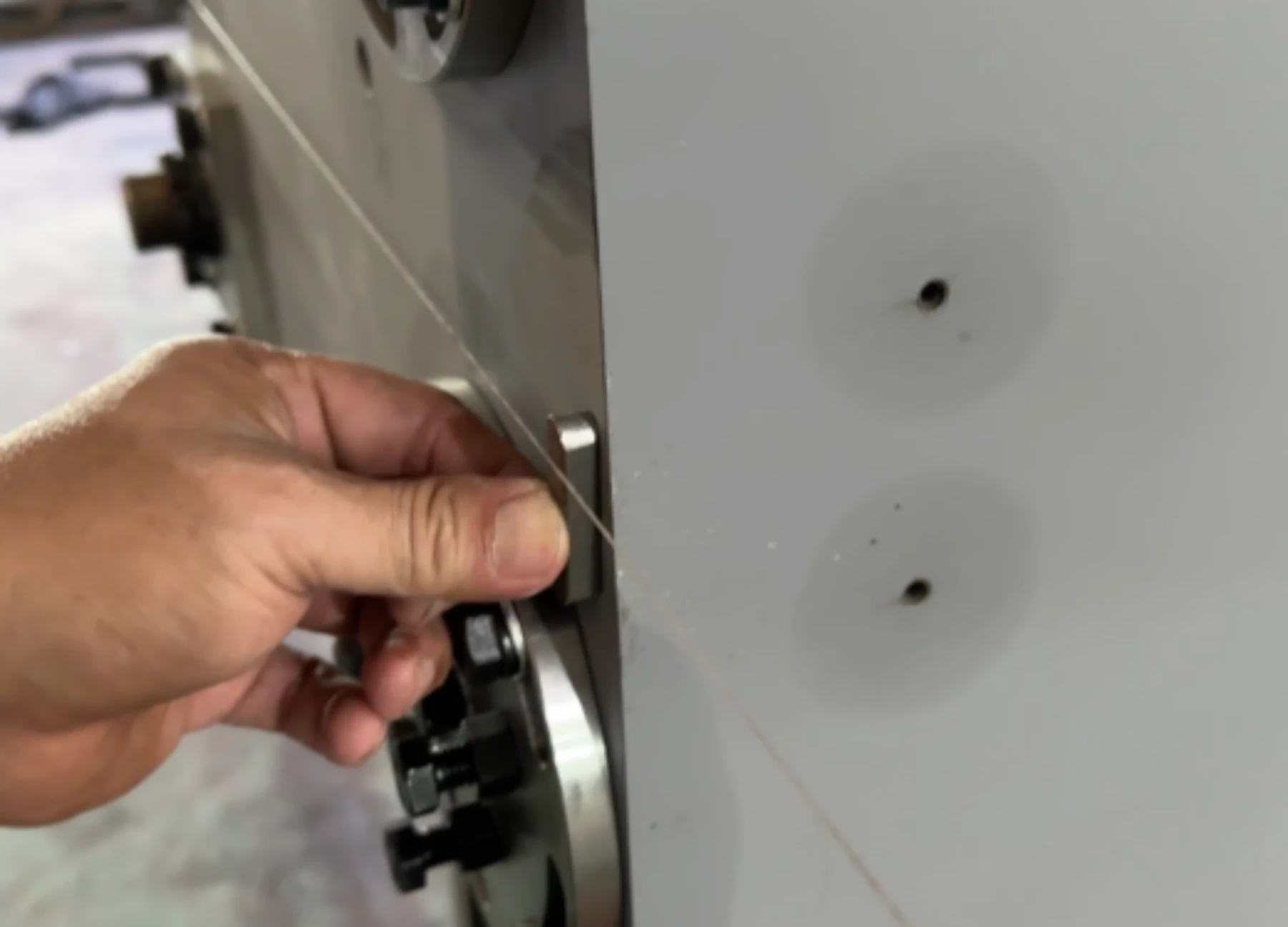
If it does not fit, adjust the bottom screw and move the column until the iron sheet fits the line (allowable error within 0.01mm) .As shown in the figure below:
By adjusting , the gasket can pass through and fit the thin line
Center distance
Measure the center points of the two columns with a tape measure, and compare the data with the foundation map provided to see if it meets the standard (allowable error: within 5mm)
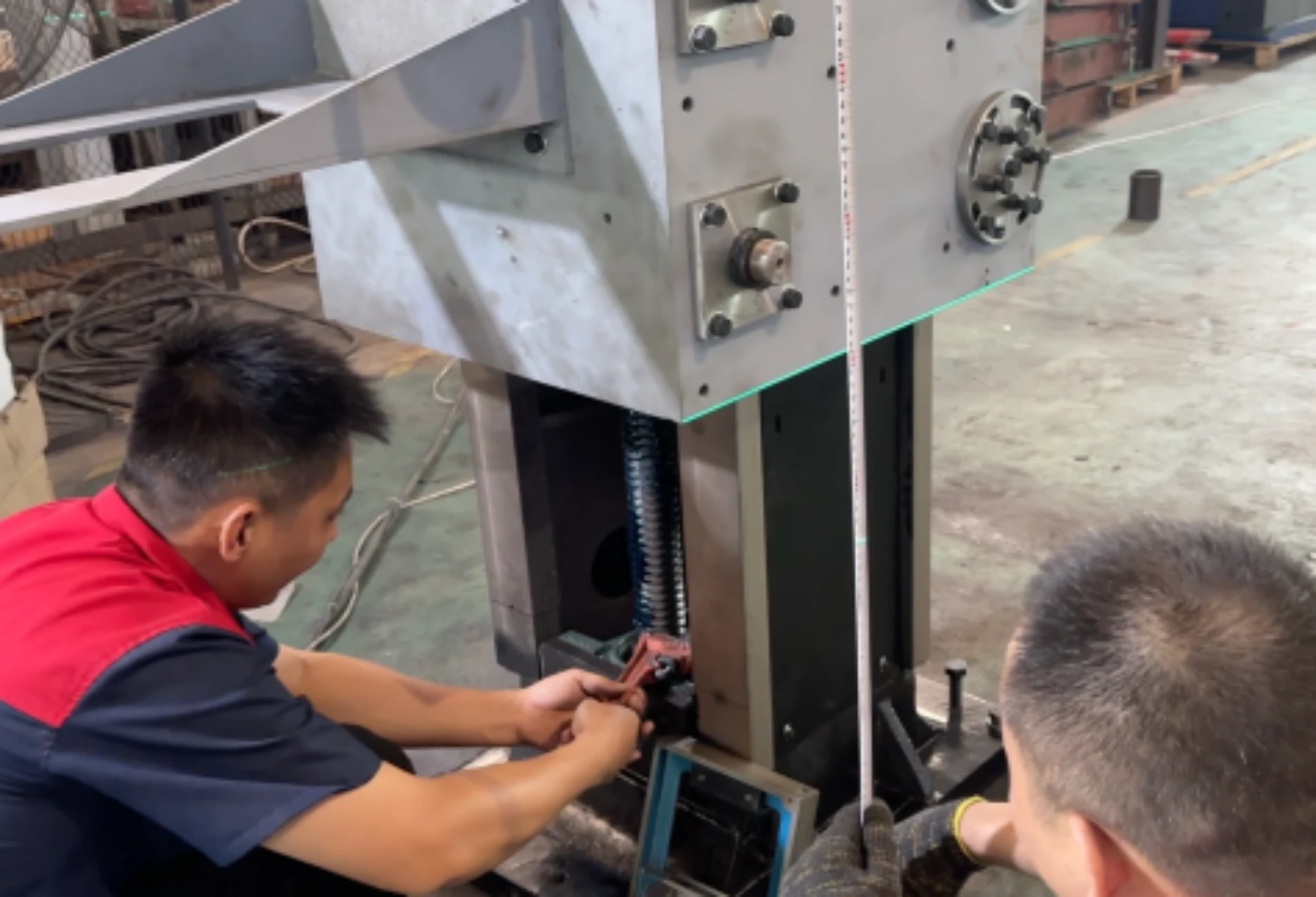
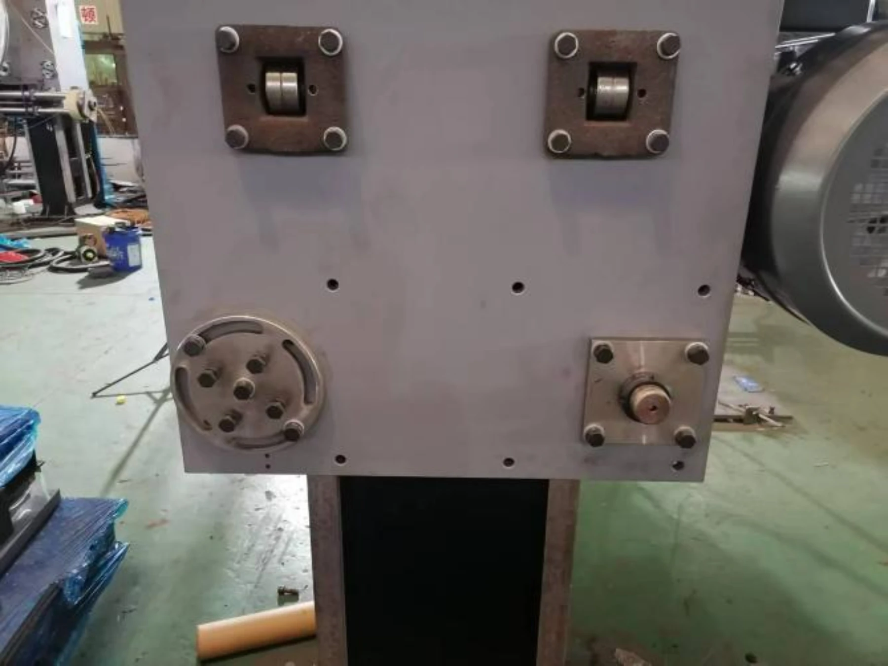
Calibrate the level of main motor boxes
Calibrate the level based on the center of the spindle.
Put an infrared level device on ground, and illuminate the square box horizontally.
Pull the tape measure vertically at the center of the spindle of the main motor box, let the infrared ray stay on the tape measure, and remember the irradiation size data.As shown in the figure below:

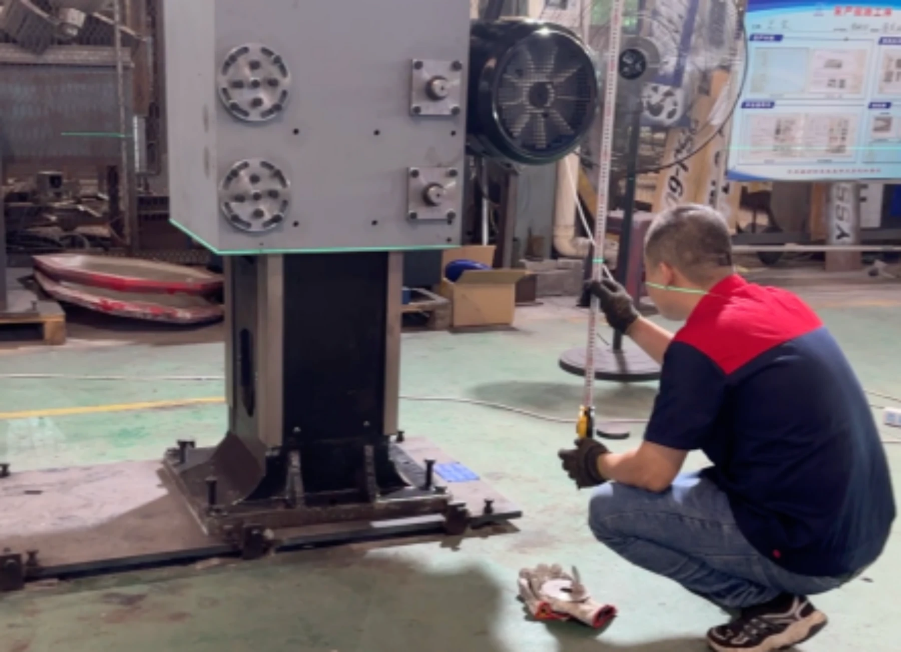
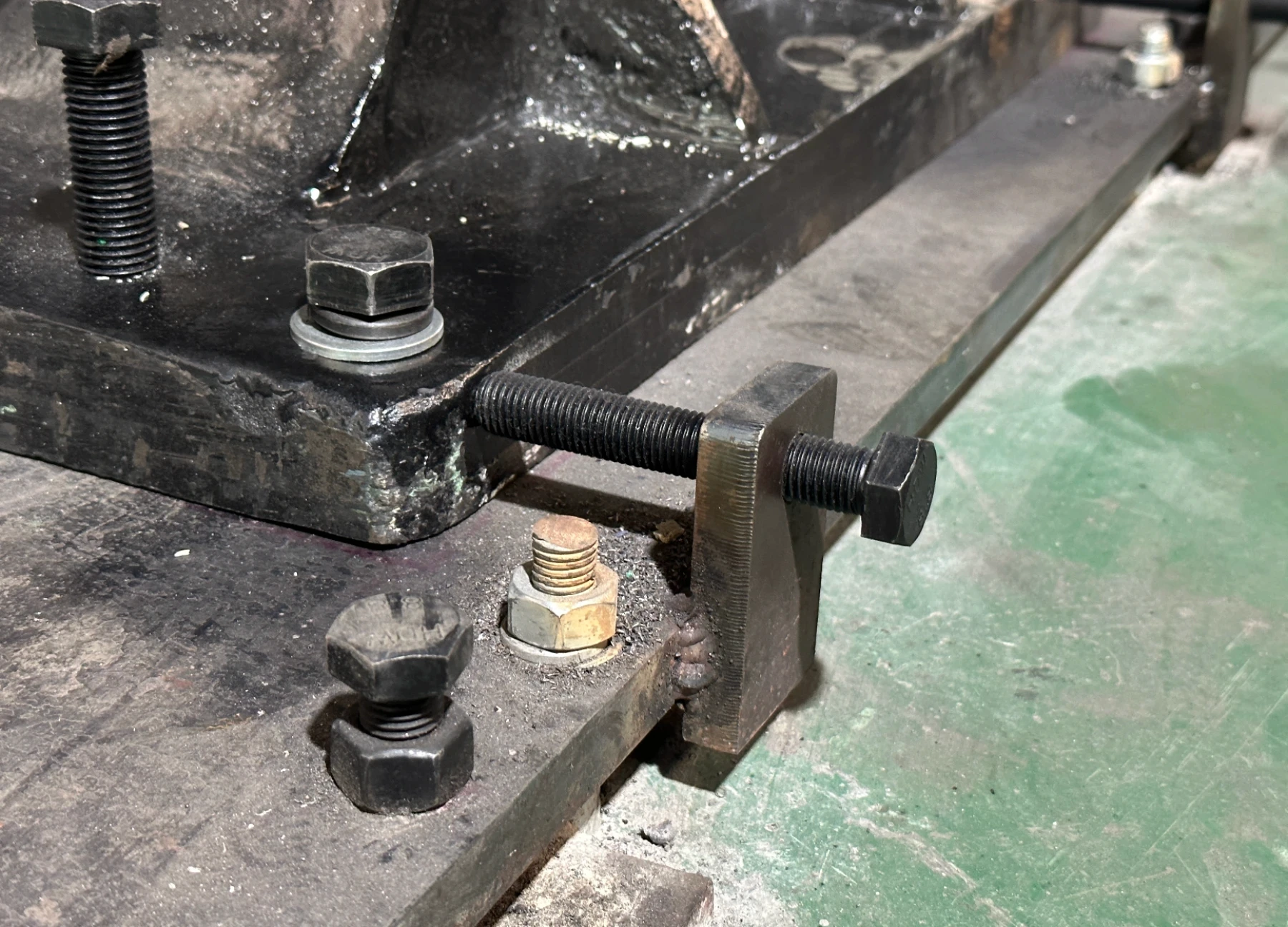
Go to the other side of the column and operate in the same way to check whether the data is the same as the recorded data; if the two data are different, manually rotate the column screw to lift (Figure 3) until the slave box reaches the same horizontal data.As shown in the figure below:
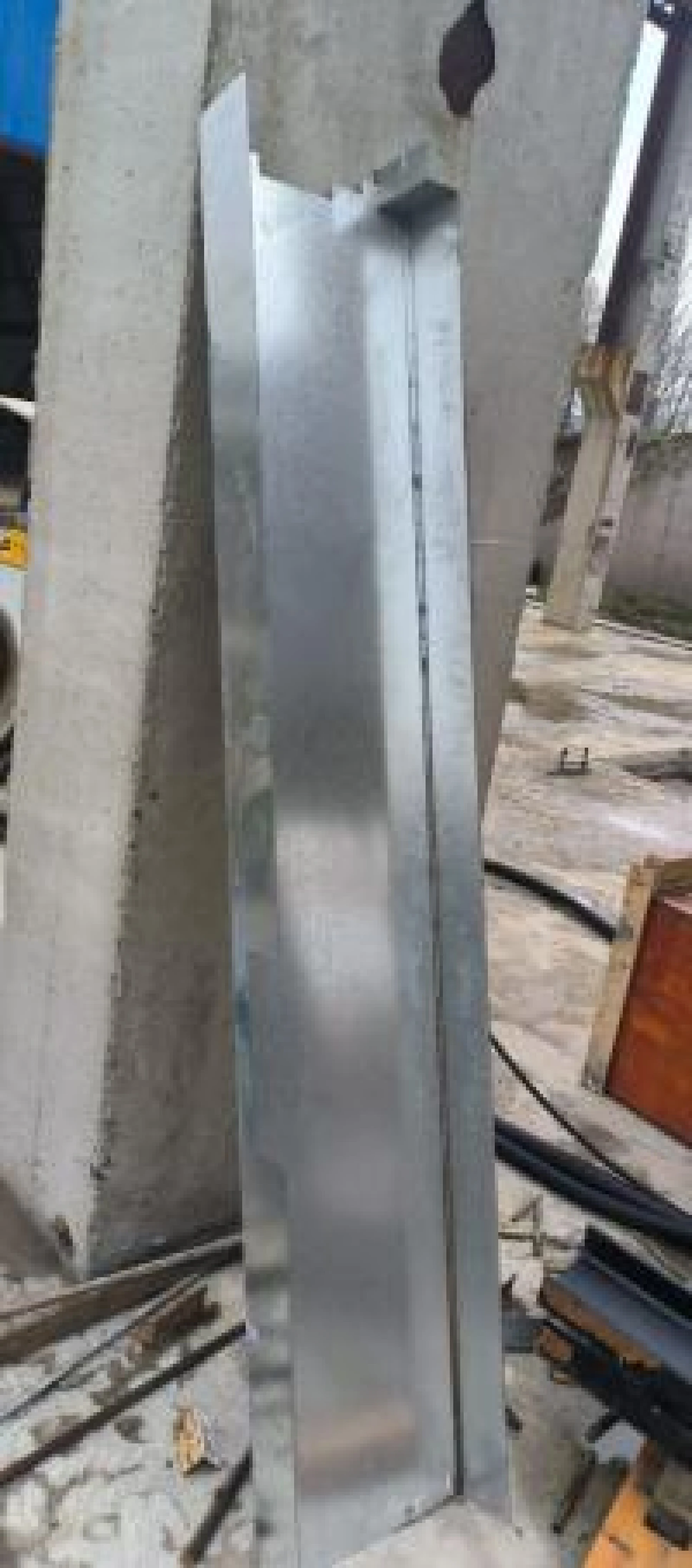
Install the cover on the column
The cover should be marked up and down.
Install the cover vertically through the square box from top to bottom, and tighten the screws at the corresponding positions.As shown in the figure below:
the cover
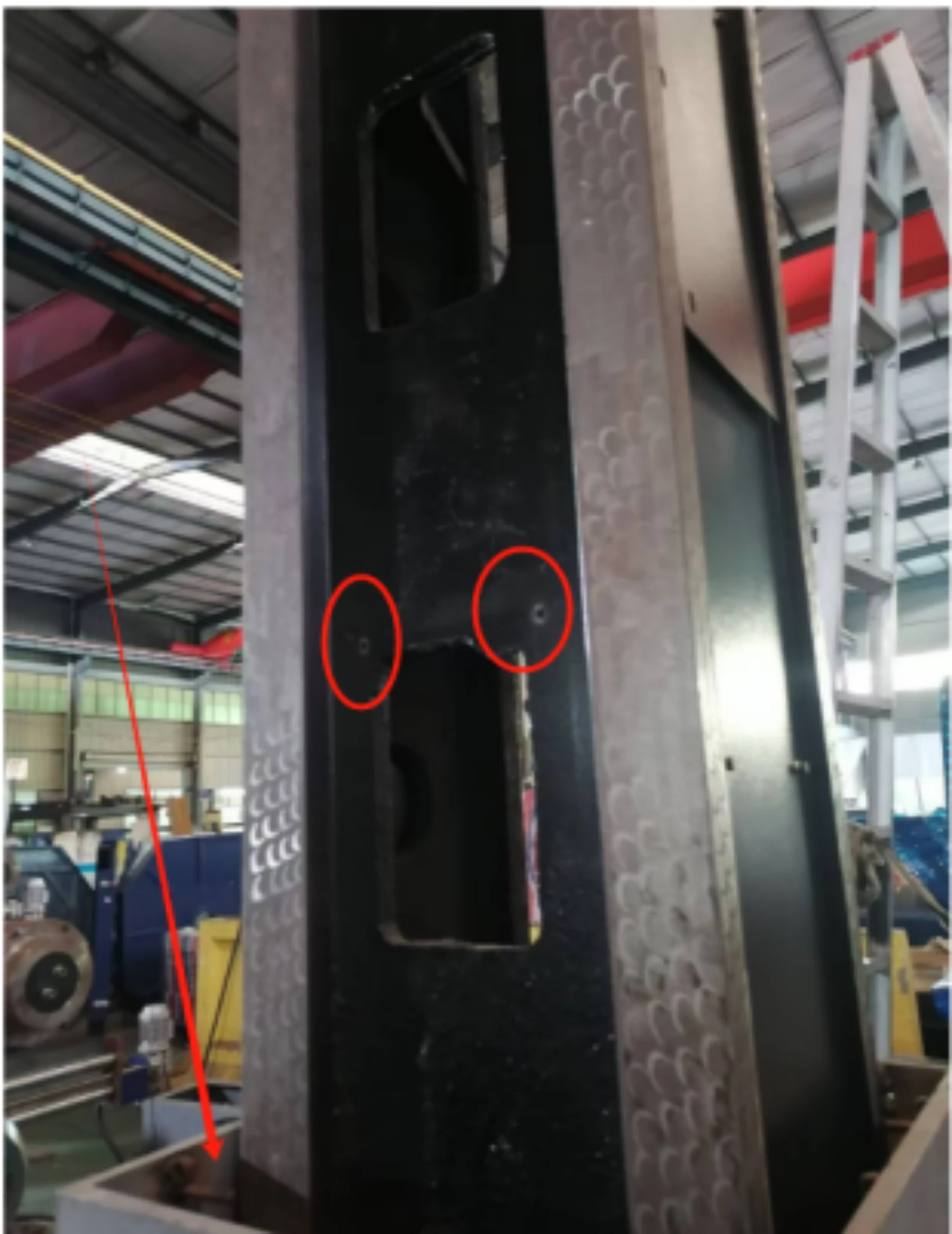
some screw hole positions
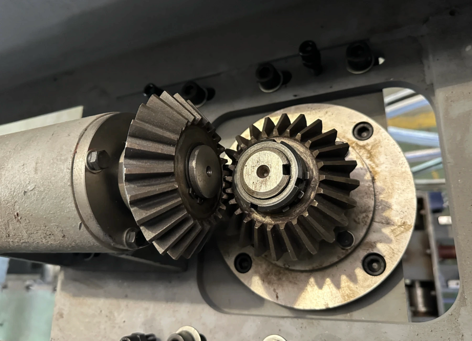
Cross Beam installation of CNC wire saw machine
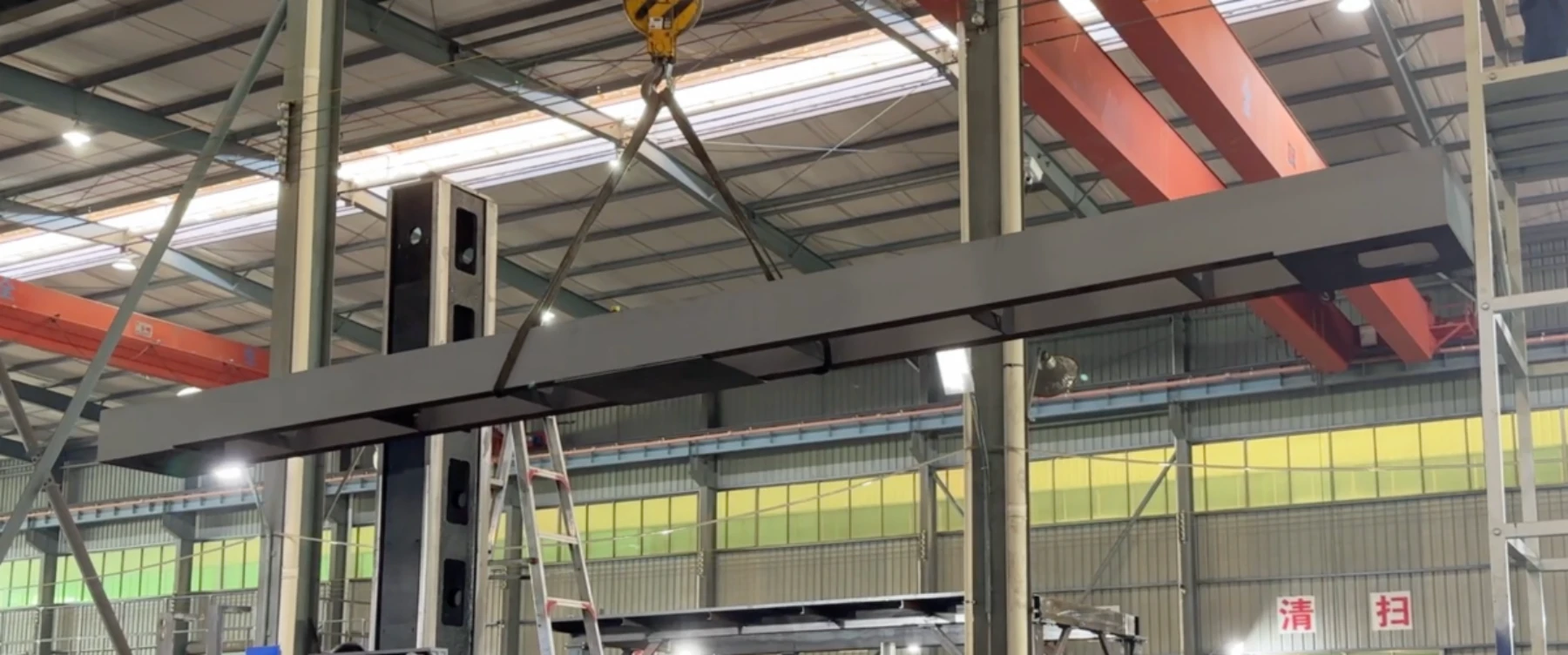
Locate the lifting center of the beam, lift it steadily and fix it on the top of the column.As shown in the figure below:
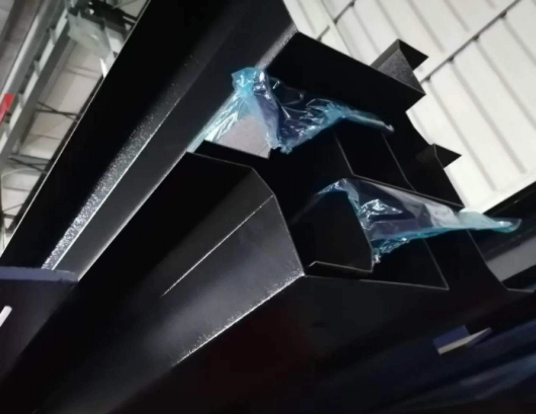
Align the center of the column bevel gear with the center point of the beam bevel gear, fit it tightly, fix the position by adjusting the screws, and lock it.As shown in the figure below:
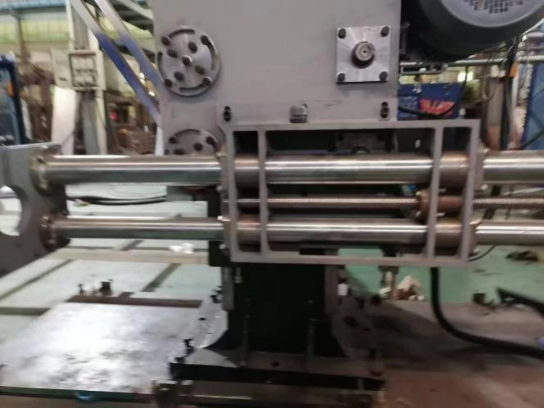
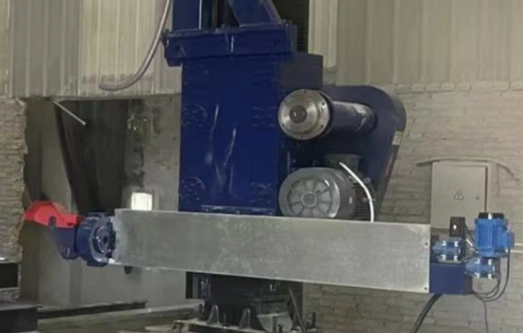
Guide wheel component Installation of CNC wire saw machine
install it on the square box according to the hole position as below shown pictures, adjust the level
Finally, and install the sheet metal cover
the sheet metal cover
the sheet metal cover install positon
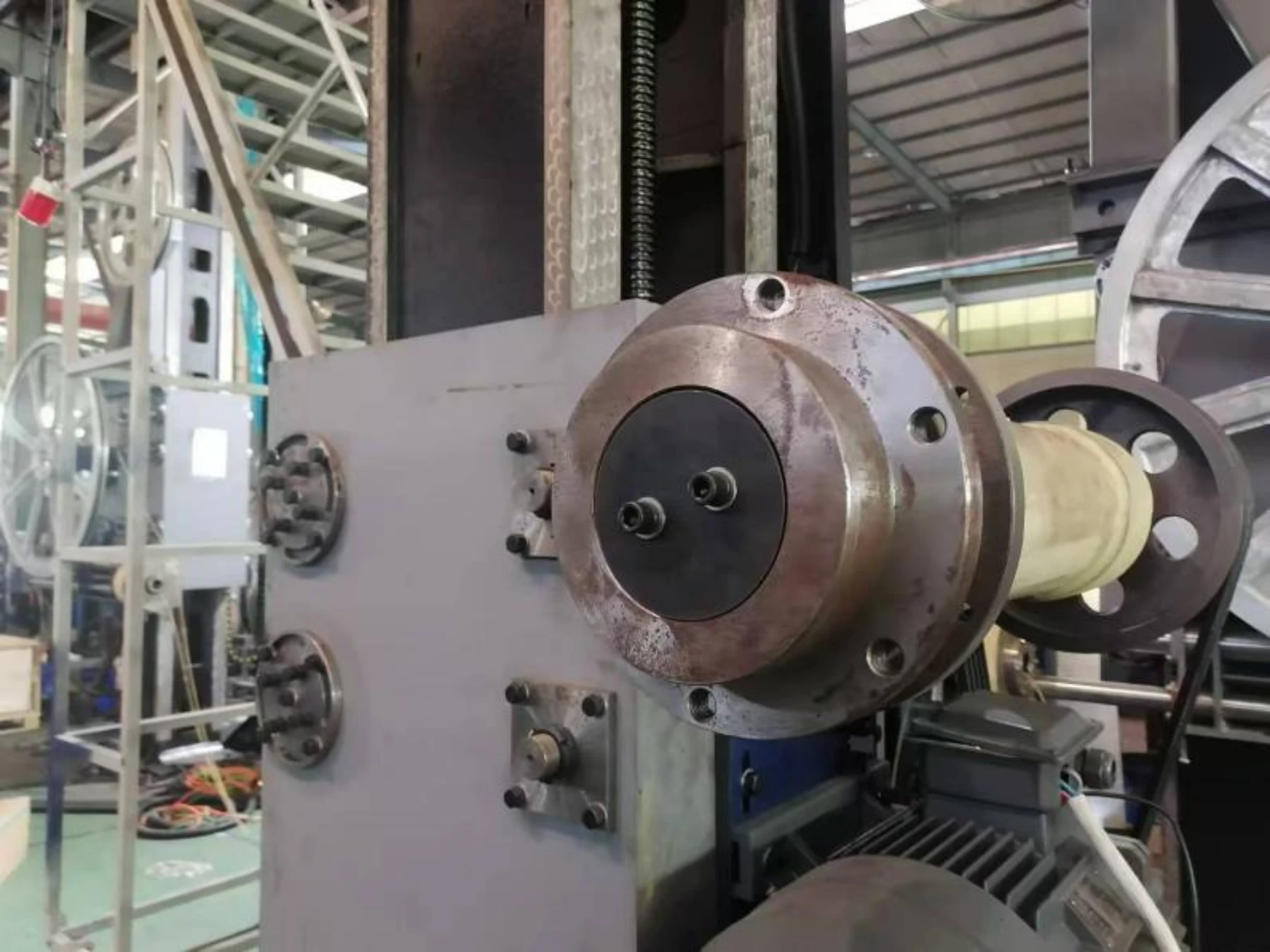
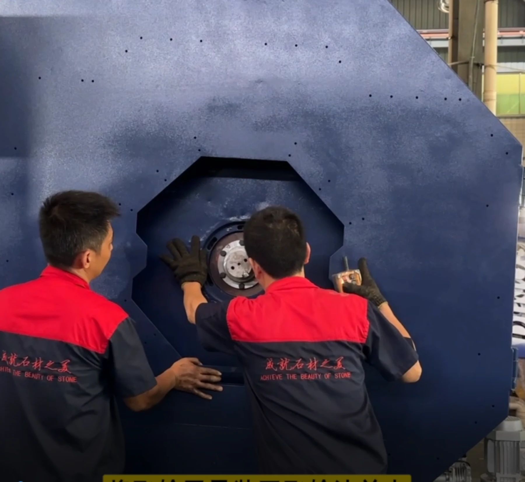
Fly wheel cover installation of CNC wire saw machine
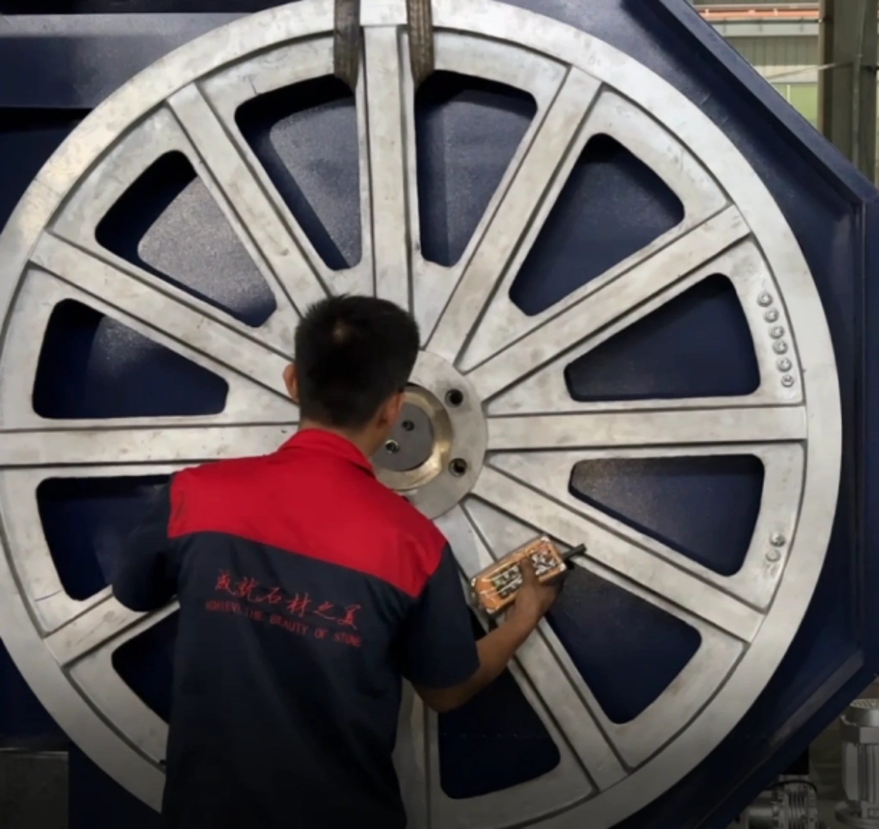
Dismantle Flange then install fly wheel as follow pic:
Install the flywheel cover. put level close to the guard to ensure that the guard is vertical and level. As follow pic:
Then install the flange pressure plate back (put lubrication oil before installation flange), and tighten all screws as follow pic:
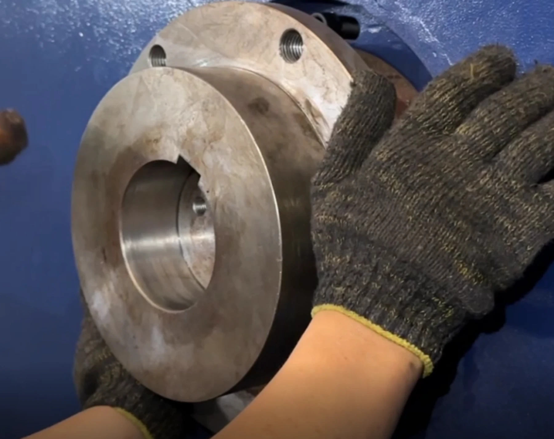
Install the flywheel onto the flange. Hold the outer ring of the flywheel and slowly rotate it to push the flywheel forward. Align the holes (if the holes are not aligned, use a tool to cross-clamp the screws on the pressure plate and rotate the flywheel in the opposite direction to align the holes) as follow follow pic:
Conclusion of CNC wire saw machine installation
The steps outlined above summarize the installation process for the YXSJ-4000 model CNC wire saw machine. Please note that while there may be some differences in details for different models of CNC wire saw machines, these basic steps are applicable to most CNC wire saw machines. If you encounter any problems during the installation process or need specific guidance for other models, please feel free to contact us at any time. We are happy to provide assistance to ensure the smooth installation of your equipment. Thank you for reading.