

Preface
Thank you for purchasing DINOSAW CNC Wire Saw Machine. Before using the machine, please read this guide to ensure safe and proper operation.
This manual covers everything you need to know for safe setup, use, and transport of the machine. It includes details on production, processing, and the machine's configuration.
It also contains operation files, control device instructions, and a list of technical data. Check this list for any additional data files.
Follow the instructions carefully to prevent accidents and be mindful of your operating environment to avoid risks.
If you need technical support, please contact us.
Copyright and related files are owned by Dinosaw Machinery Technology Co., Ltd. Any changes, photocopies, or copies of this manual must be authorized by our company. We reserve the right to update technical documents and correct any errors.
Please note that due to technical updates, there may be minor discrepancies between this manual and the actual machine. If these do not affect performance, you can still use this manual, and we will update it as needed.
Safety instructions of CNC Wire Saw Machine
Before using this control system, please read this CNC Wire Saw Machine manual carefully before performing related operations.
Safe operation
Carefully read the machine system operation and user safety requirements, and take necessary safety precautions. If the user has other needs, please contact us.
Mechanical danger
There is potentially dangerous for operating and maintaining an automatic equipment, User should be work carefully to avoid personal injury. Try to stay away safety distance from the working equipment, use the panel keyboard or manual control box to operate the equipment.
High voltage danger
Be careful of electric shock and perform safe equipment installation according to the installation procedures and specifications. Do not touch the cables or wires when electric switch is open. Only technician can open the equipment. User need to close power switch immediately when problem happened, otherwise it may cause personal injury or equipment damage.
Electricity isolation
Please check whether power supply voltage is correct (AC220V ± 15%).
When the power supply voltage range is exceeded, an AC stabilized power supply must be added to ensure the normal operation of the control system without damage.
For areas where the power supply is not standardized (such as earth line sharing or without zero line),should use isolation transformer to change three-phase or two phase AC380V into two-phase AC220V, in order to ensure the normal operation of the control system, improve system reliability, and ensure operator safety.
For working environments without lightning rods, lightning protection devices must be installed to ensure system safety.
Working environment
The working environment temperature for control system is 0-50℃. When the temperature is higher than 50℃, the system may work abnormally or even crash. When the temperature is too low (minus zero), the LCD monitor will display abnormally.
The relative humidity should be controlled at 0-85%.
When working in high temperature, high humidity, and corrosive gas environments, special protective measures must be taken.
Prevent dust, metal dust and other debris from entering the control system.
System connection
The system input / output 24V power cannot be used as a power source for other device. When this power is not connected and the emergency stop and limit are set to be valid, the system will be in the emergency stop and limit state.
The wiring from the system to the motor driver should use a good shielded wire.
It is strictly forbidden to plug or unplug any connection plug while the power is on.
The input / output lines of the system should be reliably connected.
Well grounded
All parts of the control system should be connected well with ground in order to ensure the normal operation of the control system, improve the reliability of the system, and ensure the safety of the operator.
The ground wire should be bigger than 4 square millimeters, and the distance from the ground end should be shortened as much as possible.
The 24 V DC ground (negative end) must be disconnected from the ground.
System protection
Keep the control system isolated from the external environment to prevent dust, metal dust and other debris from entering the control system, which will cause the control system to malfunction, damage system components, and reduce system life.
The LCD screen (fragile) of the control system should be protected: keep it away from sharp objects, prevent objects in the air from hitting the screen. Do not use your fingers to point, draw, or tap on the screen; when the screen is dusty and needs to be cleaned, gently wipe it with a soft paper towel or cotton.
Other Matters
The system can use a U disk, but the U disk is not in the standard configuration and needs to be prepared by the user.
The various connection cables and wires of the system are not included in the standard configuration, and users should explain them in advance when needed.
It is free only one "Concise Manual for Use" provided with the product.
It is not covered by the warranty if damage to the system due to non-compliance with safety instructions.
Control system open and close
The system is a core of numerical control system, it should be performed according to the system's operating requirements.
Control system open
When the system power is started, the system automatically boots into a start screen of the control system software. And then open power switch.
Do not open or close the system power frequently, otherwise it will easily cause damage to the control system or switching power supply.
Control system closed
After the operation is completed, when the control system needs to be turned off, the power of the driver should be turned off first, and then the power of the control system should be turned off to avoid malfunction of the motor caused by interference.
Precautions during system operation
After the system is started, enter the control software to ensure that the various parameters of the system are correct before operating various functions.
During the automatic operation of the system, try not to use extraneous keys on the operating system panel, otherwise unpredictable system errors will occur.
Operation and maintenance of control system
Operators should be strict training before operation. The system needs a professional operator. Other people are strictly prohibited from starting the system and opening electrical cabinets etc.
System operation
When operating the system, you need to press the corresponding operation button. When you press the button, you must press it with the index finger or middle finger. Do not press the button with your nails, otherwise it will cause damage to the key mask and affect your use.
For the first time, the operator should understand the correct operating of the corresponding function before performing the corresponding operation. it is strictly prohibited to operate or change unfamiliar parameters.
For problems during operation, telephone consultation service is available at any time.
System maintenance and protection
Keep the control system isolated from the external environment to prevent the system from working abnormally, damage to system components, and reducing system life due to dust, metal dust and other debris entering the control system.
The LCD screen (fragile) of the control system should be protected: keep it away from sharp objects; prevent objects in the air from hitting the screen; do not use your fingers to point, draw, and knock on the screen; when the screen is dusty and needs cleaning, apply soft Wipe gently with a paper towel or cotton cloth.
System overhaul
When the system is abnormal, please cut off the system power first when you need to repair the corresponding hardware or socket connection.
Operators without strict training or unauthorized units and individuals cannot open the control system for maintenance operations, or they will bear the consequences at their own risk. When a system failure occurs, please contact our company in time.
Statement
System warranty instructions
Warranty period: twelve months after the date of shipment.
Scope of warranty: During the warranty period, any failure that occurs under the conditions of operation according to the requirements of use.
During the warranty period, all cost for repairing faults that outside the warranty range are needed to be paid by customer.
Outside the warranty period, all cost for repairing are need to be paid by customer.
The following conditions are not covered by the warranty:
Any human or accidental failure in violation of the requirements for use;
Damage caused by plugging and unplugging the system while it is live;
Damage caused by natural disasters, irresistible factors, etc .;
Damage caused by unauthorized dis assembly, modification, repair, etc. without permission.
System upgrade and service
If there is any inconsistency between this manual and the system functions, the system software functions shall prevail.
Control system functions are changed or improved (upgraded) without notice.
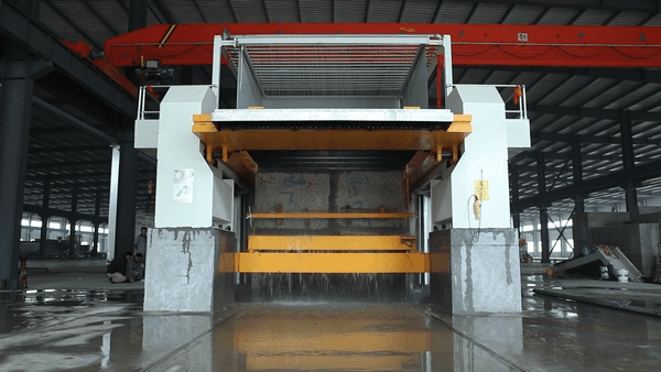
Summary of CNC Wire Saw Machine
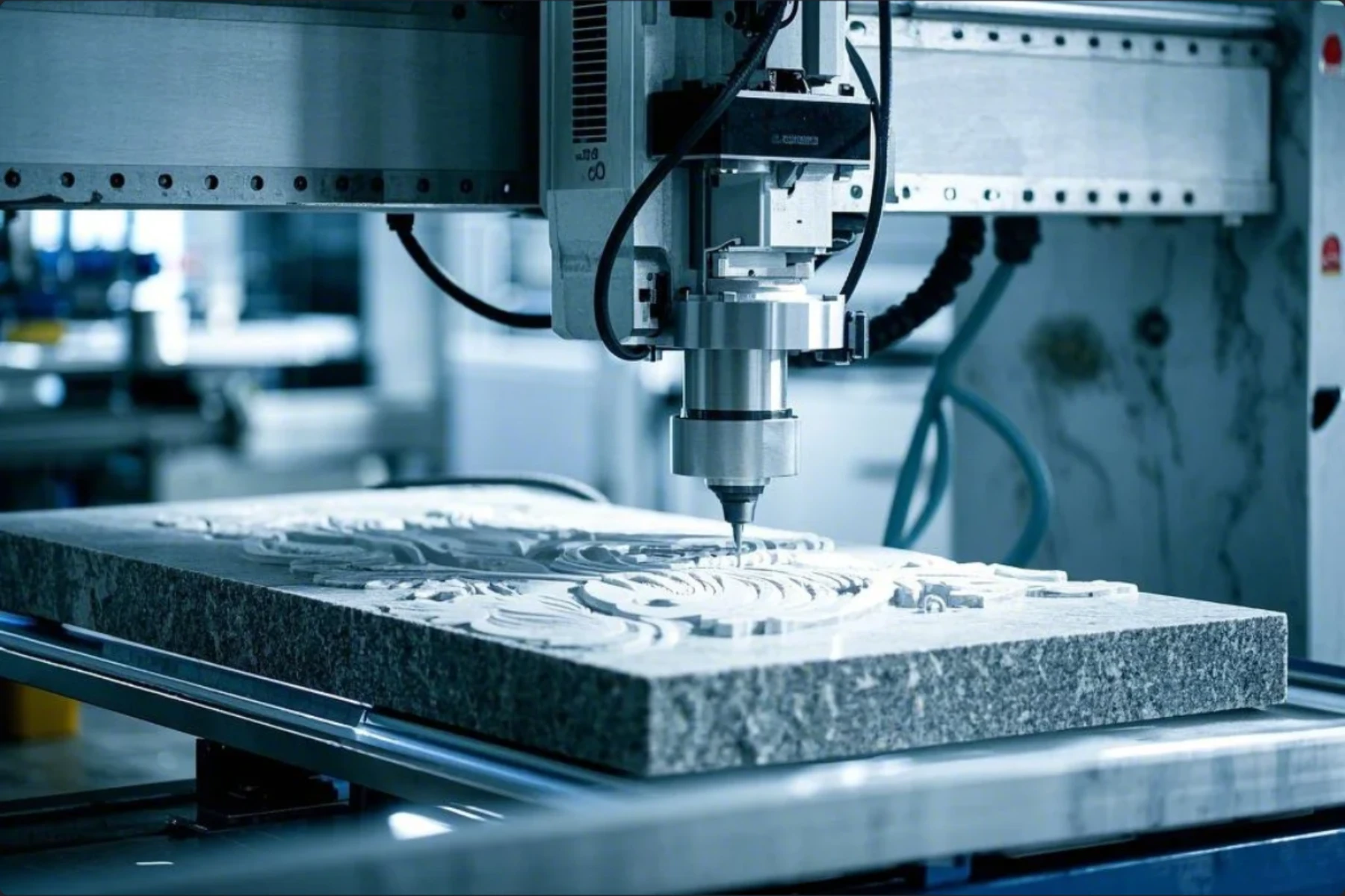
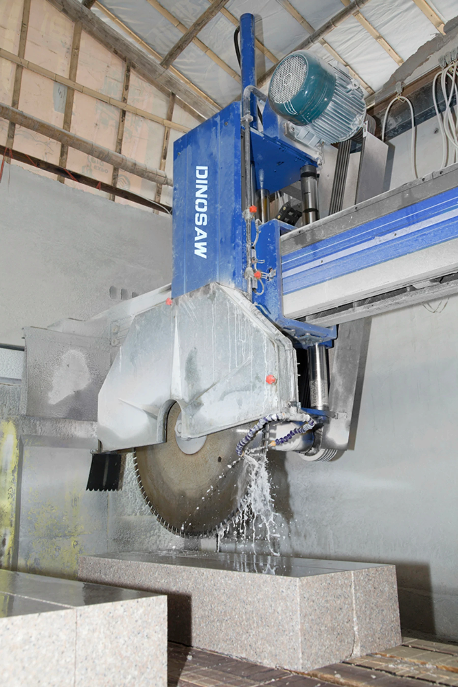
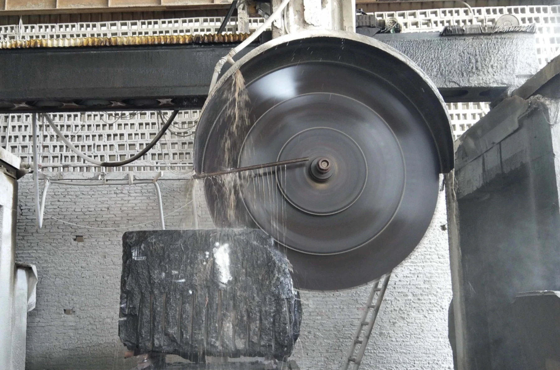
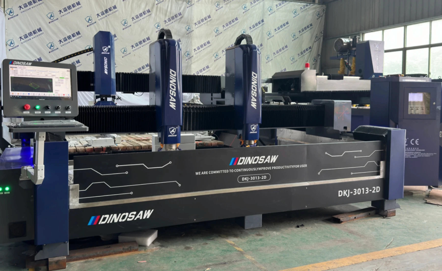
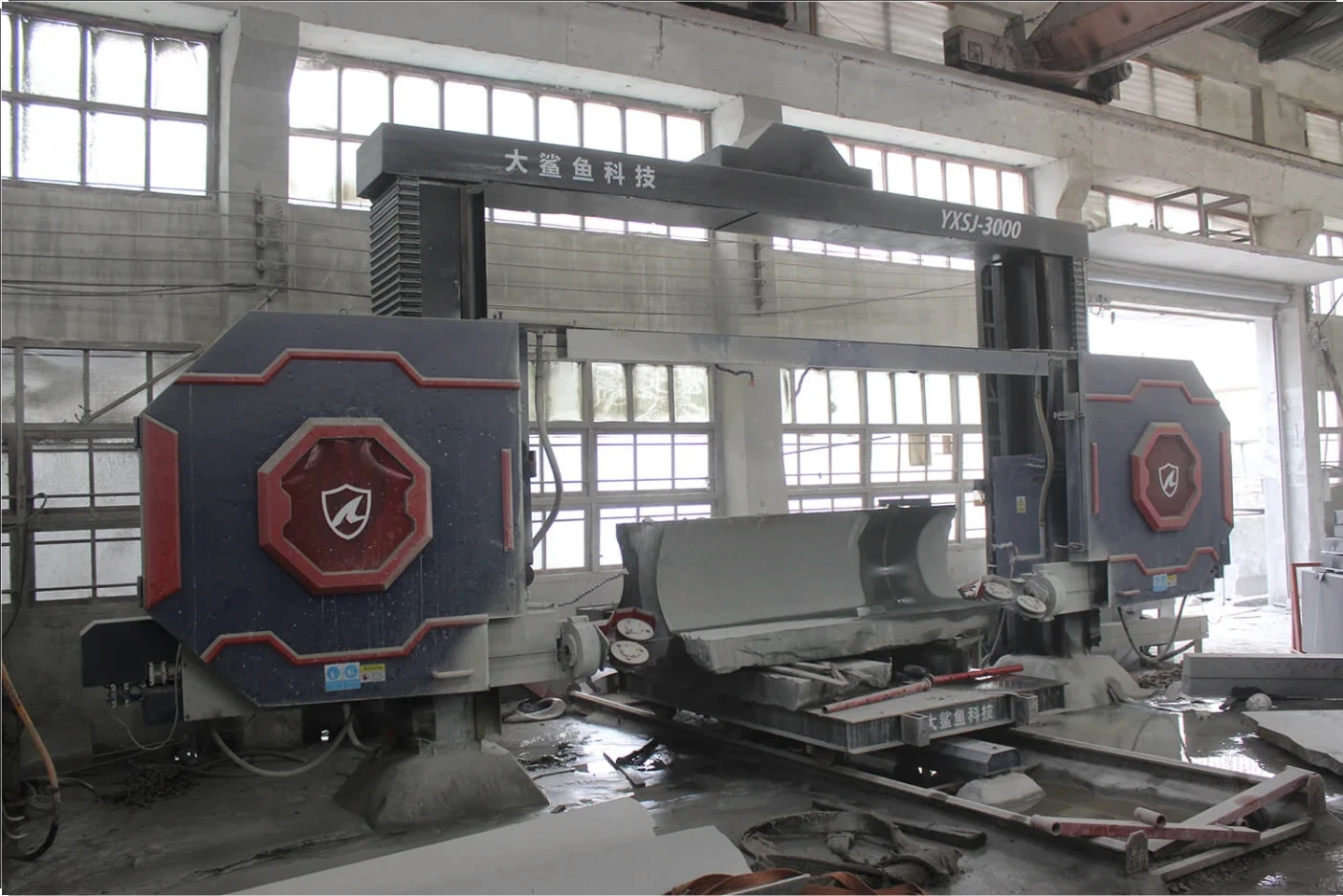
This control system is specially designed for wire saw profile cutting of stone. It can achieve two-dimensional cutting, with guide wheel coordinated automatically at the meanwhile, or rotated separately. The ultimate goal of the design is easy to use and more humanized human-computer interface.
High performance industrial touch panel adopted, special interpolation controller, anti-interference processing, powerful software function, precise processing method, which allow position fixed of control system exacter. The equivalent weight can be controlled to 1μ. The highest speed can reach 500mm/m(under 1μ equivalent weight). The adjustable up and down treatment makes the running of the equipment more smooth and stable, and display dynamic position of the cutting equipment precisely (precision to 1μ). The function of dynamic graphics allows to check the graphic trajectory of whole cutting process.
The wire saw is equipped with 1024*768 CLCD, full closed touch operating keyboard, AC servo motor for driving device and 24V machine tool electrical control interface. This system is featured by great functions, good reliability, high precision, low noise, easy operation, small size, light etc.
Panel appearance
Instruction of main screen
Instruction of main window of control system
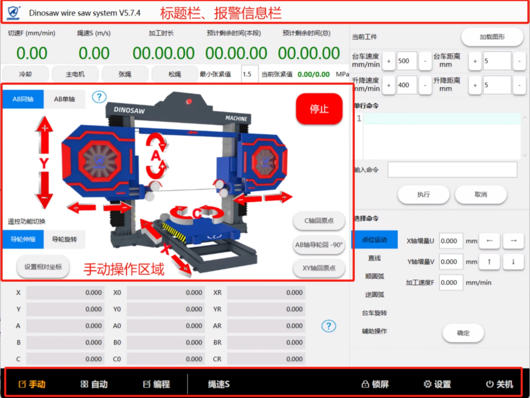
Title bar includes system name,version number and warning messages (when there is multiple alarms, the earlier alarms will be displayed sequentially, the rest will not be displayed if out of range).
Menu bar includes buttons of manual, automatic, program, screen lock, setting and help.
Processing information area will display processing information of present processing workpiece (processing speed, linear speed, processing time, estimated remaining time for this segment, and estimated remaining time for whole processing.
Operation area is composed by machine operation area in left and order operation area in right.
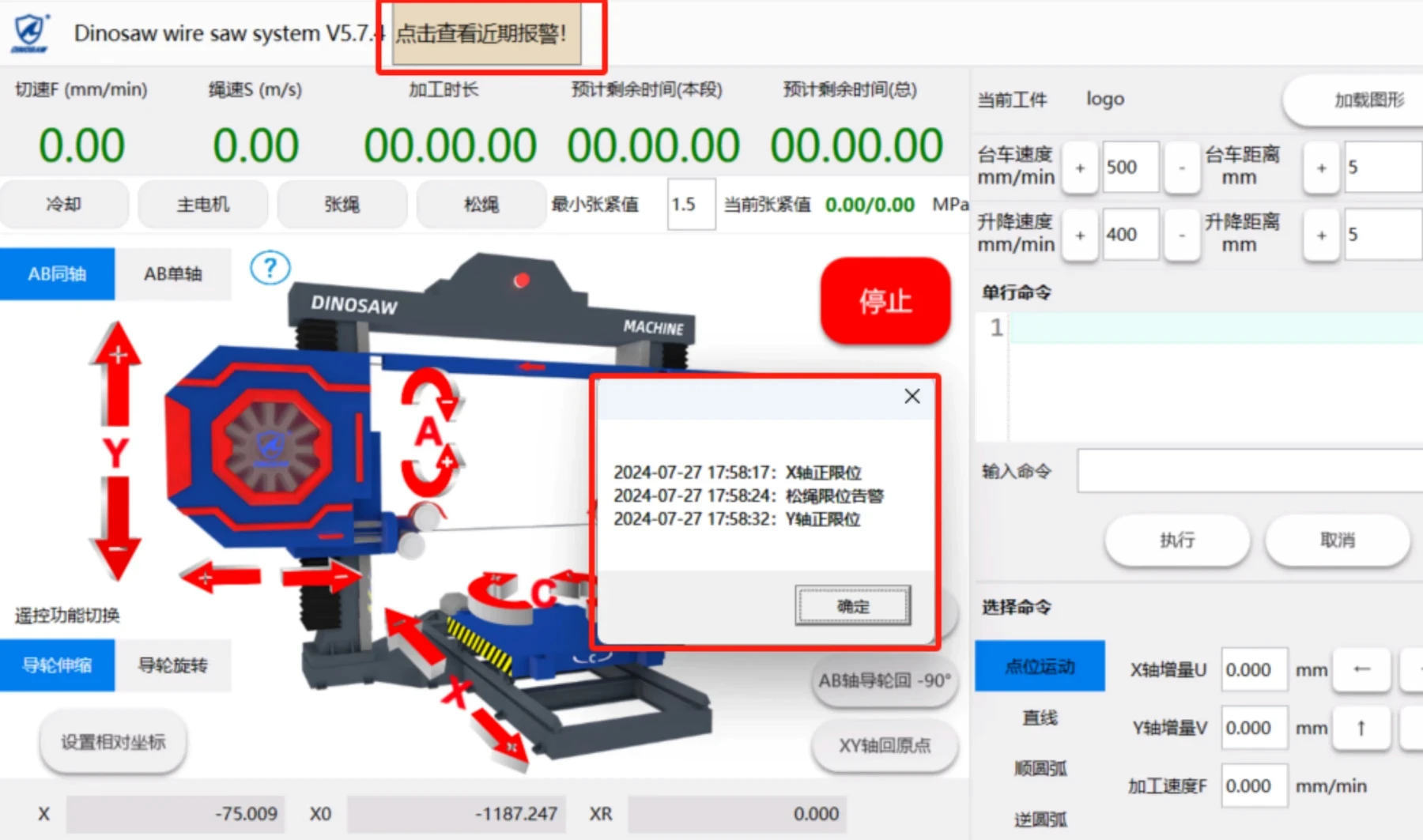
"Click to view recent alarms" function: After the wire saw system is started, it will record abnormal problems during this operation and the time of the problem, so as to facilitate the troubleshooting of equipment abnormalities at any time.
System configuration
Control system unit
Industrial level 14 inch touch panel
Dedicated motion controller (signal output: + 5V TTL, differential output)
Input / output interface (32 optical isolation inputs, 9 optical isolation outputs)
U disk interface
Fully enclosed case
Drive unit
X-axis stepping (subdivision) driver or servo motor driver
Y-axis stepping (division) driver or servo motor driver
A-axis stepping (subdivision) driver or servo motor driver
B-axis stepping (division) driver or servo motor driver
C-axis stepping (division) driver or servo motor driver
Technical indicators
Minimum programmable unit 0.001mm
Maximum programming size ±99999.999mm
Maximum arc radius 400000.000mm
Rapid point movement speed limit 9000mm / min (when pulse equivalent is 0.001mm)
The maximum processing speed limit 9000mm / min (when the pulse equivalent is 0.001mm)
Maximum pulse output frequency 150KHz
Number of control axes 5 axes (X, Y, A, B, C)
Number of linked axes Straight two to four axes, arc (XY plane arc)
Electronic gear Numerator: 1-65535, Denominator: 1-65535
System main functions Program processing, parameter processing, program management, manual, setting, self-test, simulation,etc.
Full Chinese menu and tips Switch between Chinese and English
Full screen multiline text editing Maximum editable length of 32K bytes
Program management Read program, save program, new program, delete program, read U disk, write U disk, read DXF, etc.
Maximum number of segments per file 1000 lines, the maximum length 32K bytes.
Maximum user program capacity 2M
Main functions
Setting: Various control parameters related to processing and operation can be set up.
Through reasonable setting of parameters, the processing effect can be optimized.
Program upload and download: Through the system U disk interface, the current program can be uploaded to the U disk for storage, and the processing program in the U disk can be downloaded as the current program.
Program preview: You can observe the outline of the program in the file list to facilitate selection of files.
Unique input anti-interference processing: Digital filter processing is performed on all 32 input points to make the input stable and reliable.
Input / output port setting function: Any input / output port can be specified (the same output port cannot set up more than one function).
Manual: manual operation functions: manual point movement, single line command processing, zero return, set coordinates, etc.
Editing: program editing, reading, writing & deleting, U disk reading and writing, standard slabs, DXF graphics generation program, etc.
Automatic: graphics, single segment, segment selection, breakpoint, back off, back to starting point, simulation, etc.
Parameters: Set up parameters related to processing, self-test, etc.
Manual: Display this instruction manual embedded in the control system.
Menu display: dynamic graphic display makes operation intuitive and convenient.
Multi-languages: Chinese, English, Russia, Spanish.(Other languages are available as per request.)
A variety of standard slabs programming: making processing and programming of conventional workpiece more convenient.
Pause processing: It can realize the functions of back off and resume after the pause.
Graphic processing trajectory display: dynamic display of the central trajectory during the current processing.
Graphical simulation: dynamic simulation, fast and accurate graphic displaying of processing process (no signal output)
Electronic gear: Electronic gear ratio can be set up arbitrarily to match various mechanical structures. Note: The electronic gear ratio is better when numerator ≤ denominator.
Breakpoint processing: if power interruption during processing, or exit after processing is suspended, processing can be continued at the original processing point.
Manual of CNC Wire Saw Machine
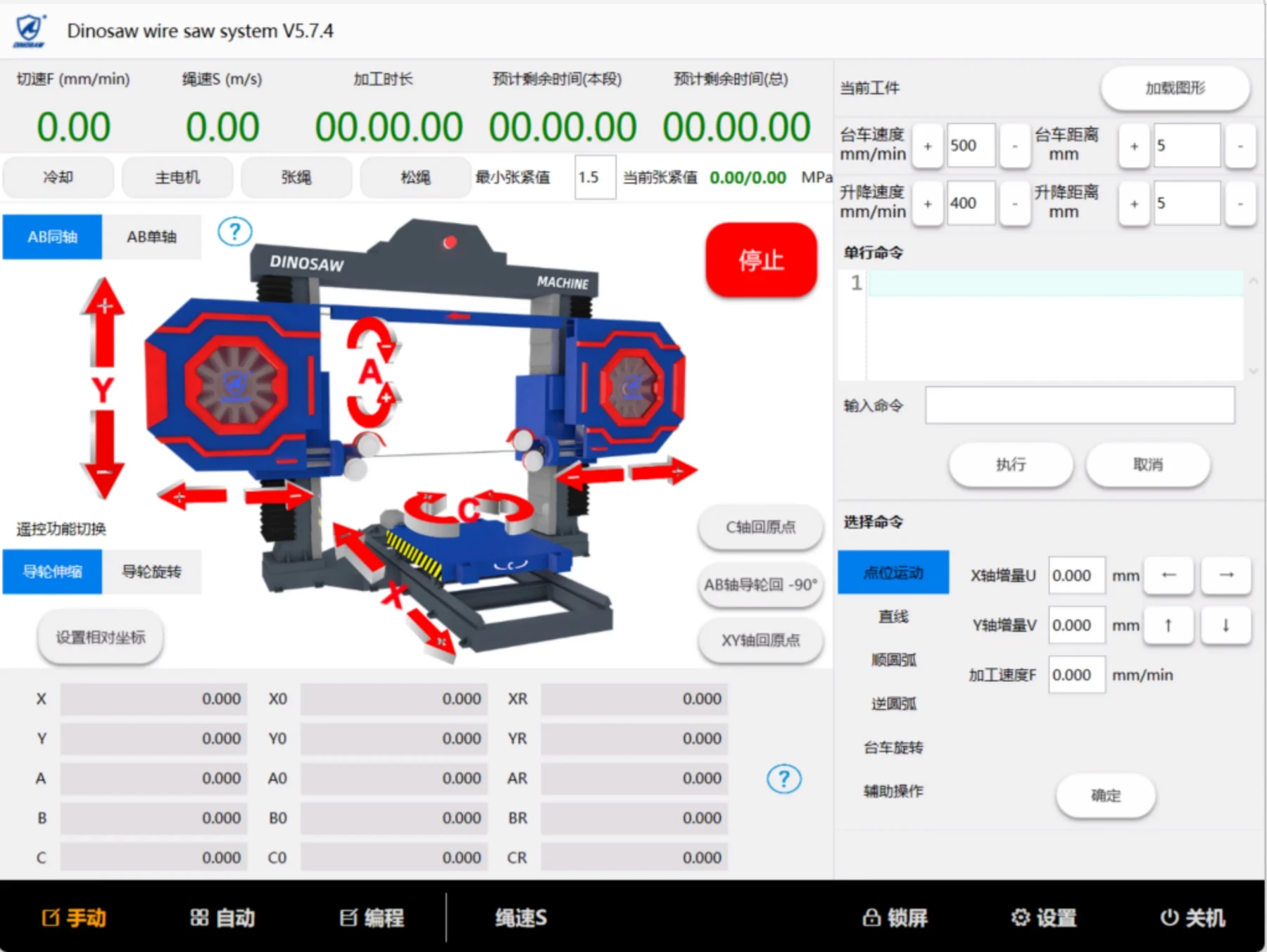
Main window: Click the <Manual> button to enter the manual operation screen (default main page).
Output control
Cooling: control the turning on and off of the cooling water (when turned on, the status is green)
Main motor: control the start and stop of the main motor (in operation, the status is green)
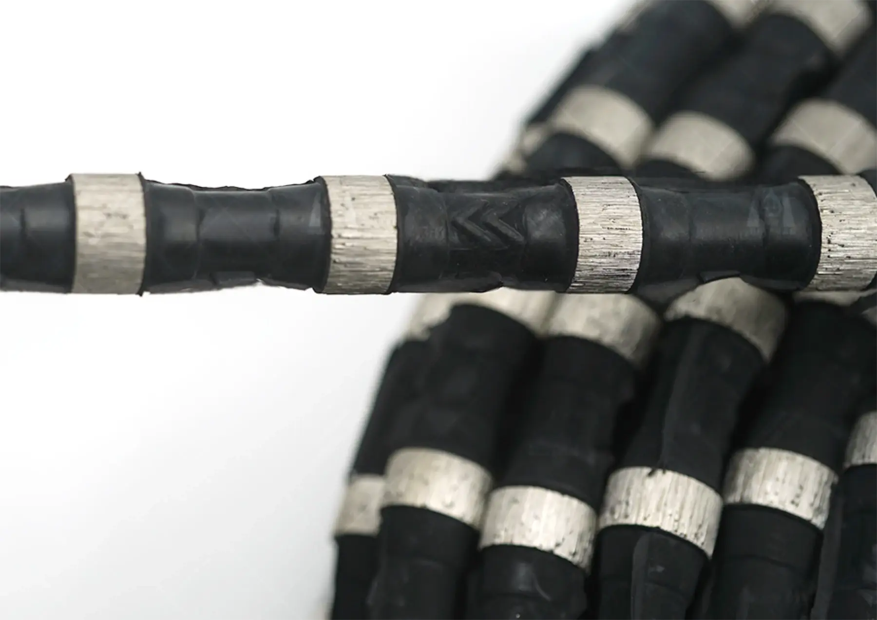
Tensioning rope: Tensioning wire saw
Loose rope: loosen the wire saw
Tension value: set the lower limit of the pressure of the wire saw during automatic pressure holding
Manual operation
Parameter setting
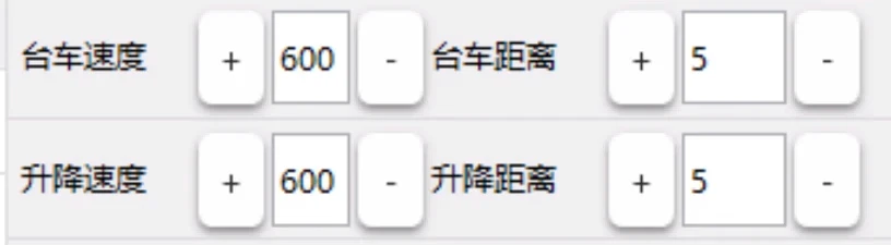
Set the moving speed (mm / min) of the trolley (X-axis), lifting platform (Y-axis) and the moving distance (mm) per click
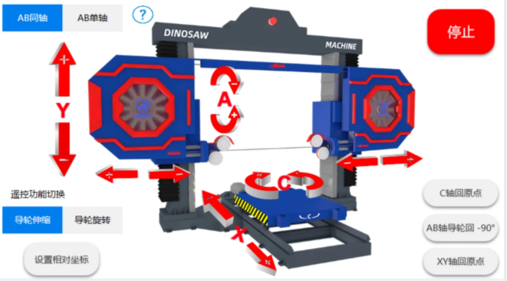
Click each axis button (X,Y,A,C,Z1,Z2), you can move each axis in the positive or negative direction. As long as you hold the key, the equipment will keep moving. When you release these keys, the equipment will slow down and stop smoothly.
Key Description:
X +, X-: make X axis move positive and negative directions.
Y +, Y-: make Y axis move positive and negative directions.
A +, A-: Make AB axis move at the same time, or single A axis move positive and negative directions, related to AB coaxial / AB single axis state.
C +, C-: Rotate the C axis clockwise and counterclockwise.
Z1 +, Z1-: Make the left guide wheel telescopic rod extend to left and right.
Z2 +, Z2-: Make the right guide wheel telescopic rod extend to right and left.
AB coaxial / AB single axis: Switch the movement status of AB axis. When A axis is operated coaxially, two axes move synchronously. When A axis is operated by single axis, only A axis moves.
C axis return to origin: rotate the C axis to the set origin
XYAB return to origin: move XYAB axis to the set origin
Stop: Immediately stop the movement of each axis
Set relative coordinates: Set the current tool head position to the corresponding relative position.
Single line command
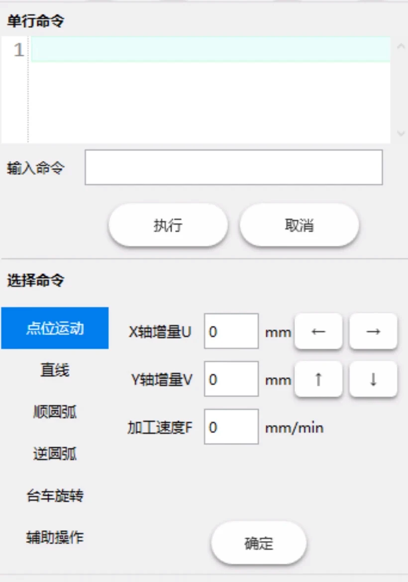
The input single-segment command controls the movement of the machine. When the execution is not completed, the next program segment can be entered, but it cannot be executed. It needs to be executed after the previous segment is completed. Cancel during execution.
Selection command: Quickly generate commands for controlling the machine, including point motion, straight line, Clockwise arc, counterclockwise arc, trolley rotation, and auxiliary operations. Enter the corresponding parameters and click OK to generate the corresponding command.
Coordinate setting

Click the coordinate setting button to bring up the coordinate setting interface.
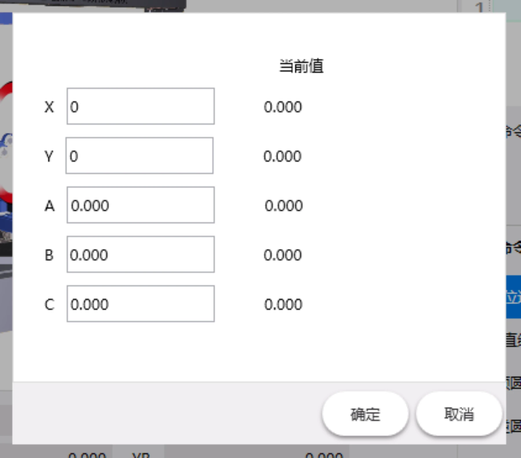
Enter the current coordinate values of each axis and click confirm.
External manual
button description
X +, X-, Y +, Y-, A +, A-, C +, C- can be manipulated through input points. This function is only effective in manual mode. During operation, one direction, two directions, and three directions can be pressed simultaneously, but the positive and negative directions of the same motion axis cannot be pressed simultaneously.
The manual control of the external manual control box is controlled by the system's AB coaxial / AB single axis status.
Instructions for manual operation
Limit switches are currently installed in the system. When the X, Y, Z1, and Z2 axes move to the limit point, they stop moving. At this point, you can move backward to leave the limit point. The angle axis of the guide wheel (A axis, B axis) and the rotation of the trolley (C axis) are infinitely controlled due to the rotation axis. Special attention should be paid to the operation.
Automatic of CNC Wire Saw Machine
Main window: Click <Auto> button to enter the automatic operation screen.
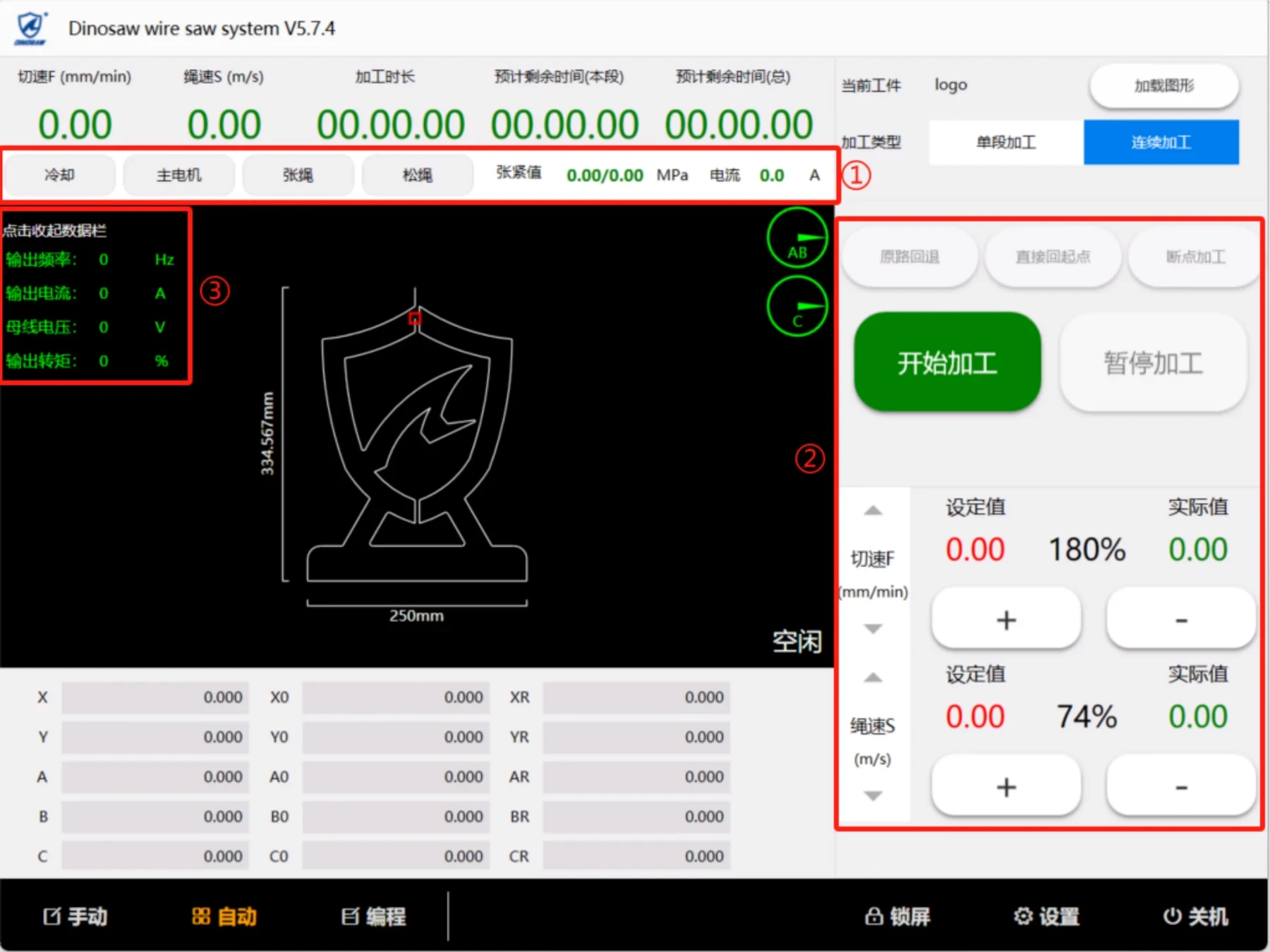
During automatically control processing, the processing graphics can be previewed and displayed dynamically.
①Spindle jog area: including water cooling (external solenoid valve to control water valve), main motor start and stop, rope tensioning and rope loosening control functions. At the same time, the real-time tension value of the hydraulic station and the main motor current are displayed.
②Automatic function operation area: including trial adjustment of cutting speed, rope speed, start and stop processing, original path retraction, etc.
③Spindle status bar: can monitor the output frequency, output current, bus voltage, output torque and other key parameters of the main motor in real time, which is convenient for observing the real-time motor performance and facilitating after-sales troubleshooting.
Menu of automatic processing functions
Load graphics

Click <Load Graphic> button to pop up the graphic selection interface
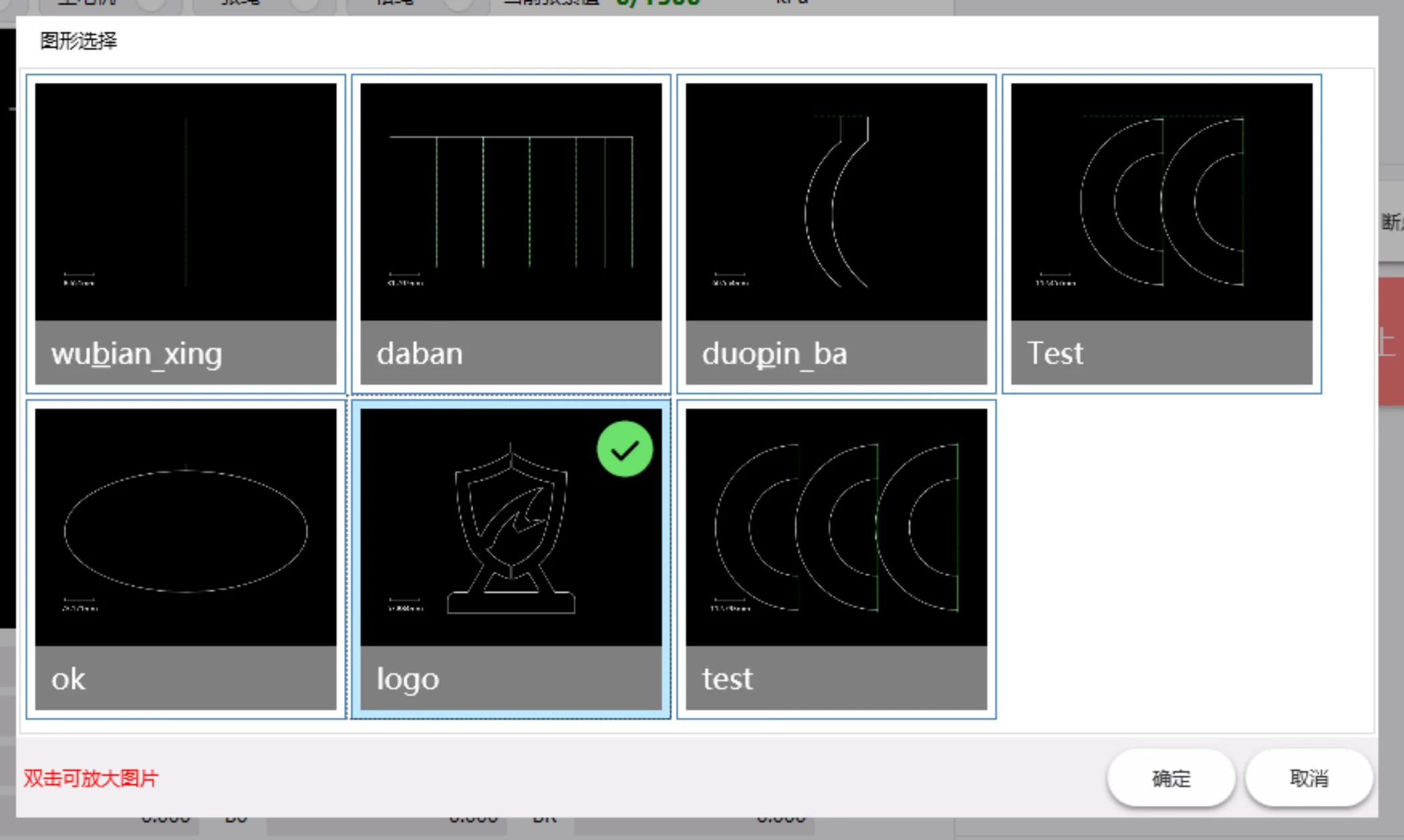
Select the graphic, and click OK to complete the operation.
Output control

Cooling: control the turning on and off of cooling water
(when it’s turned on, the status is green)
Main motor: control the start and stop of the main motor (in operation, the status is green)
Tensioning rope: tension the wire saw
Loose rope: loosen the wire saw
Processing Type

Switch between single segment processing and continuous processing.
In the single segment processing status (this button is blue), after every program line is executed, it enters the segment stop status, and wait, until the "Start" key is pressed to continue.
Processing operations
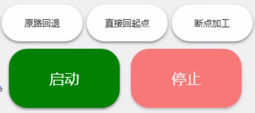
Start: Start / continue automatic processing.
Stop: Stop automatic processing.
Back off by the original path: After the automatic processing is paused, if you need to back off, you can press this button. After retreating a processing segment, the system automatically enters segment stop. If you need to continue to retreat, press this button again.
Return to the starting point directly: After processing is completed, or after pause or segment stop, this function can be used to return each axis to the starting point of processing at the nearest distance.
Breakpoint processing: The power is interrupted during the processing, or exit after the processing is suspended. If you need to continue processing at the original processing point, press this button to enter the breakpoint processing mode. Click again to cancel the breakpoint processing mode.
Preparation before automatic processing
Program preparation
After entering the main screen of automatic processing, you can switch to the graphic display state and observe whether the graphic is correct and whether it is the graphic to be processed to confirm whether to perform processing.
If there is an error prompt in the auxiliary display area when entering the automatic, please enter the "programming" function to modify according to the type of error and the program line where the error is located, and then enter the "automatic" for processing.
If the drawing and design are incorrect, please enter the "programming" function to modify it, and then enter "automatic" for processing.
State preparation
The angle of the guide wheel displayed should match its actual angle. Is the angle of the two guide wheels normal and correct?
F +: speed multiplying increase, increases rapidly after pressing for more than half a second, up to 200%
F-: speed multiplying reduction, decrease rapidly after pressing for more than half a second, minimum 0%
S +: RPM speed multiplying increase, increases rapidly after pressing for more than half a second, up to 200%
S-: RPM multiplying reduction, decrease rapidly after pressing for more than half a second, minimum 0%
Whether single segment processing is required (Execute stop after every program segment processing is completed, and wait to start.)
Whether to process from the breakpoint (This function can’t be used when there is no correct breakpoint, or program is changed.)
When using for the first time, set up appropriate processing parameters in the parameters.
Automatic processing
Main window: Click <Start> to start automatic processing. During automatic processing, it will be suspended when M00 is encountered.
Speed adjustment
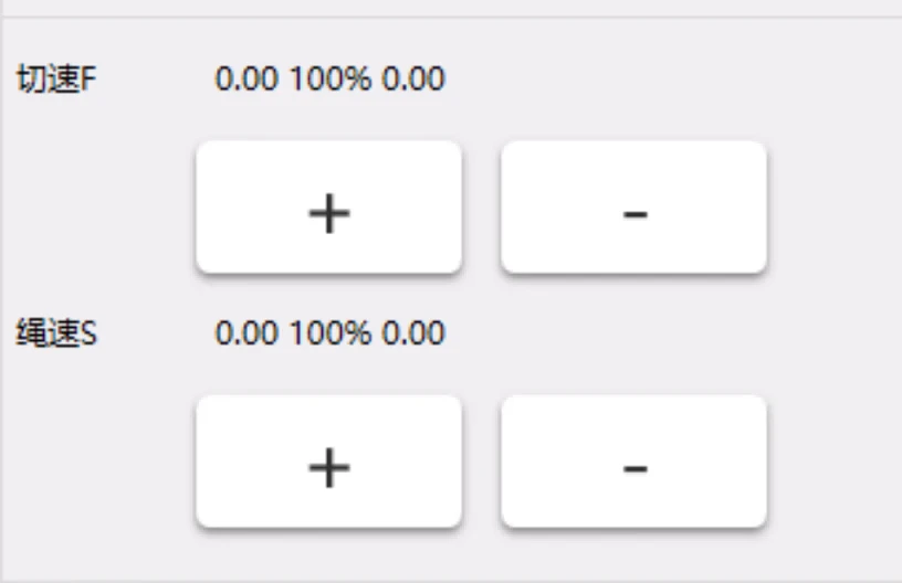
When you need to change the processing speed, click the “+” and “-” keys to increase or decrease the speed multiplying value to change the processing speed.
When you need to change the speed of the rope, click the “+” and “-” keys to increase or decrease the speed multiplying value to change the linear speed.
Note: The adjustment range is 2 times of the maximum value set.
Suspend processing
During automatic processing, press "Stop" to decelerate and stop the processing process, and display pause to enter the pause state.
In the paused state, you can press "back off by original path " to enter the processing back off. You can press "Start" to continue to enter the processing state.
Instruction of automatic processing
Coordinate display: X, Y, A, B, C are absolute coordinates of the machine.
XO, YO, AO, BO, and C0 are the absolute coordinates of the program. (Only the absolute coordinates of the program can be cleared.)
XR and YR are the residual coordinates of the current segment, and the machining residual amount of this segment.
Program display: current execution segment, display in green.
subsequent pending execution segments, shown in white.
Speed display: speed setting value, related to F speed in the program.
The current speed multiplying rate, related to the use of F +, F-
The current speed is related to the speed set value, speed multiplying rate, and the process of speed up and down.
RPM display: speed setting value, related to S speed in the program
Current RPM multiplying rate, related to the use of S +, S-
The current RPM is related to the RPM setting value, speed multiplying rate, and the maximum RPM of the motor.
Processing time: Calculate from pressing "Start" until processing is completed.
Processing delay: Count down, accurate to 1 second
I / O status: current input / output status display
Alarm display: current alarm information, the display changes once every half a second
Pause/Segment stop display: “Stop” is displayed after entering the segment stop, and "Pause" is displayed after entering the pause. This state will be displayed when exit automatic too.
Program of CNC Wire Saw Machine
Main window: click < program > button to enter the programming operation screen
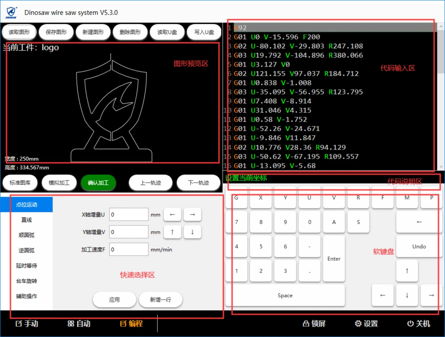
This window is used to enter or edit program code. Enter this window to display the current graphical program. If you want to save your changes to disk, you can use the save graphics feature.
Read graphics: select a graph to read from the list.
Save graphics: saves the current content as the current file name (or save if given a new file name).
New graphics: clears the current content and creates new graphics.
Delete graphics: deletes the current graphics.
Read U disk: choose to read DXF file or TXT file from U disk to the current program area.
Write U disk: write the current program area to the U disk.
Previous track: switch the current track to the first track
Next track: switch the current track to the next track
program editing function
Keys:
numeric key 0-9, decimal point ". ", negative sign "-", space (space), enter (enter), character keys G U V R F M P A,
Cursor move key: up "↑", down "↓", left "←", right "→",
Undo(Undo),
Delete key (←-),
The cursor
The up and down keys can move the cursor line, up and up, until the first line of instructions; Lower key moves down to the last line of instruction; The left and right keys move the cursor column, the left key moves forward, to the first line of this line of instructions (the first character at the left end) and then continue to move left to the end of the previous line of instructions (the last character at the right end); Right to move to the right, to the end of the line of instructions continue to move to the right to the next line of instructions;
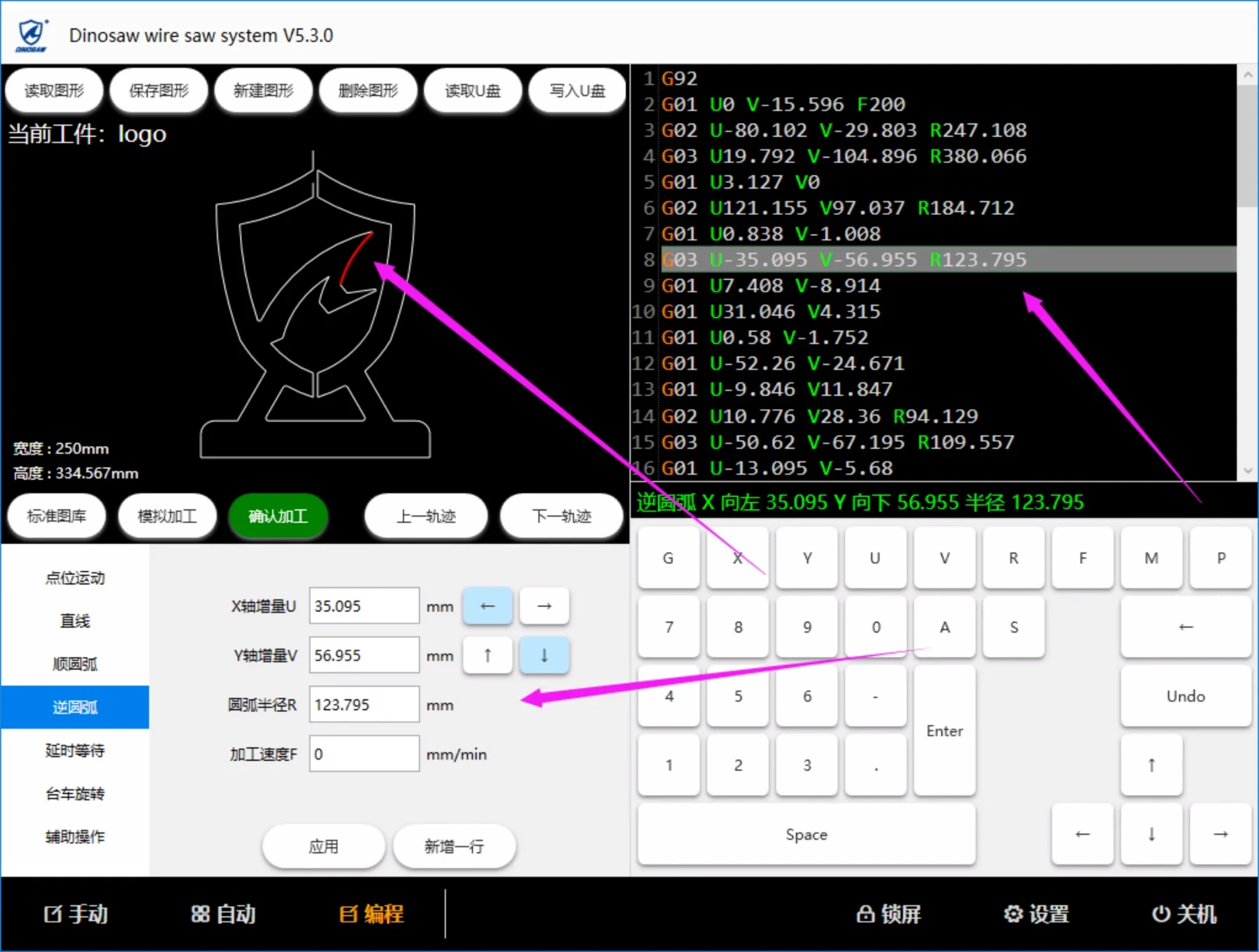
In the graph preview area, the corresponding line segment will be highlighted according to the instructions of the current line, and the parameters of the current line will be filled into the quick selection area at the bottom automatically, as shown in the figure below.
undo
Press the Undo key once to Undo an action that precedes the code entry area.
Insert a new row
Move the cursor to the beginning of the line, press "ente